Lighting device

a technology of light source and light source, which is applied in the direction of semiconductor devices for light sources, light and heating apparatus, transportation and packaging, etc., can solve the problems of limited light pattern, limited scope of lighting devices, and inability to effectively dissipate heat around the optical color wheel for light mixing, etc., to achieve the effect of dissipating hea

Inactive Publication Date: 2012-06-28
LITE ON ELECTRONICS (GUANGZHOU) LTD +1
View PDF3 Cites 23 Cited by
  • Summary
  • Abstract
  • Description
  • Claims
  • Application Information

AI Technical Summary

Benefits of technology

[0007]In one aspect, since the optical color wheel is in rotatable contact with the base, the fins of the base can dissipate heat generated by the optical color wheel in addition to the light source. Besides, the lens is movably disposed on the base, the light projection angle can be adjusted accordingly. Also, a plurality of colored petals can be disposed on the optical color wheel. When the optical color wheel rotates, light passes through different color petals to provide multiple colors of light. Hence, the color temperature of the light for the lighting device can be adjusted.

Problems solved by technology

However, heat around the optical color wheel for light mixing often cannot be dissipated effectively.
Also, the light projection angle is fixed for conventional lighting devices, meaning the light pattern is restricted.
In use, such lighting devices are limited in scope, and the color temperature of the light are fixed also.

Method used


Image

  • Lighting device
  • Lighting device
  • Lighting device

Examples


Embodiment Construction

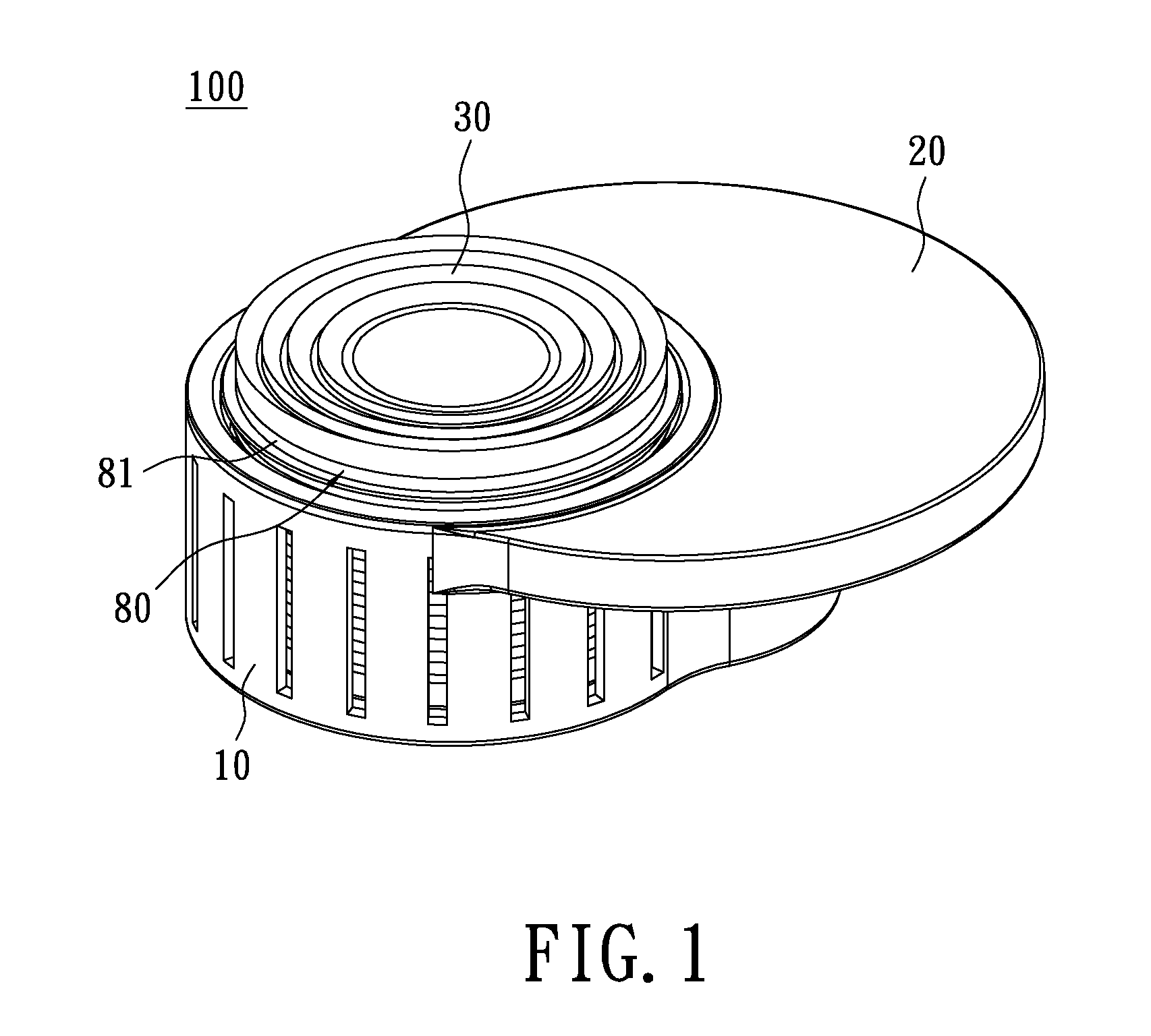
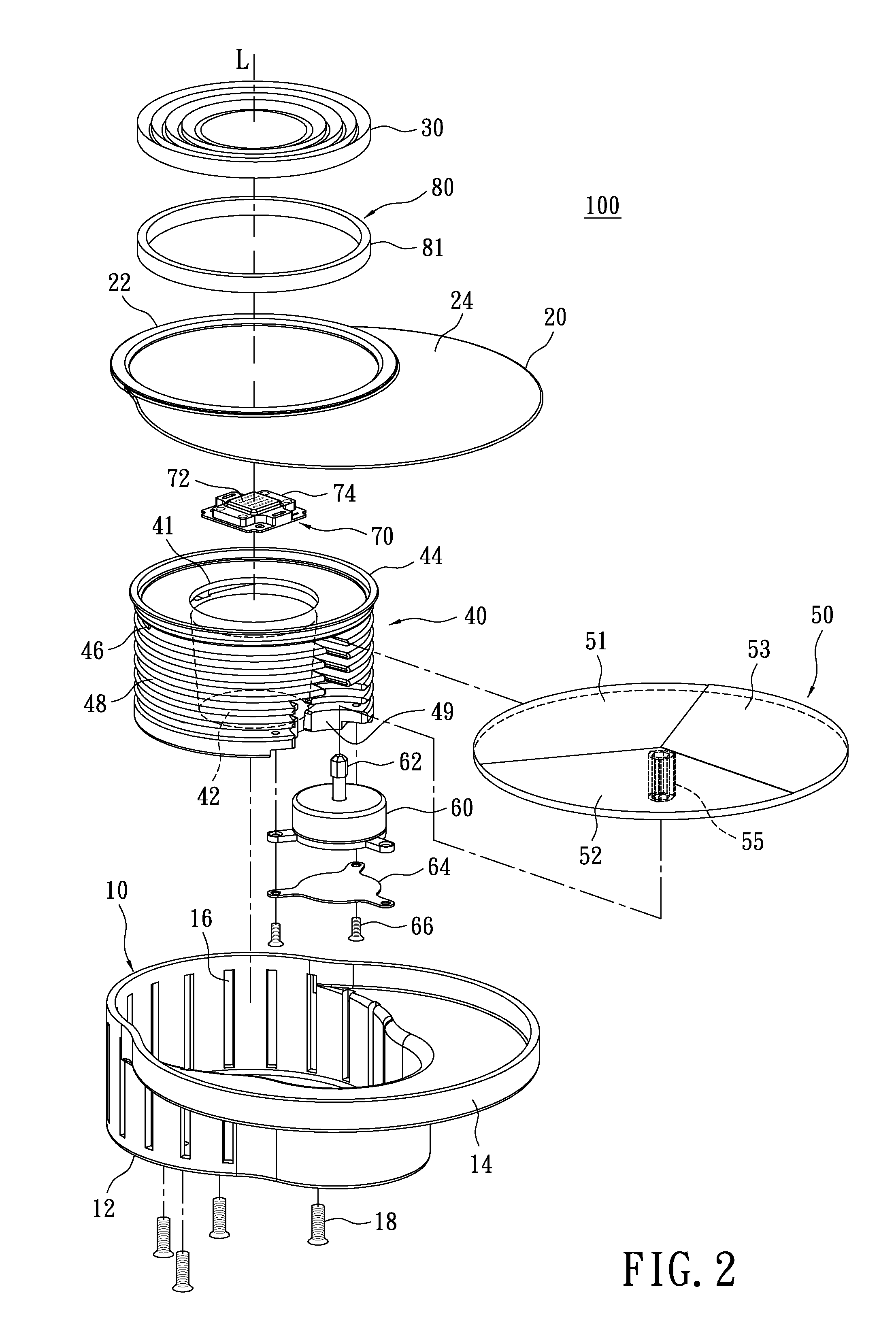
[0013]Please refer to FIGS. 1 and 2, which show a lighting device 100 of the instant disclosure. The lighting device 100 comprises a holder 10, a cover 20, a lens 30, a base 40, an optical color wheel 50, a motor 60, and a light source 70.

[0014]The holder 10 receives the base 40 therein. The base 40 has a plurality of protruded fins 48 for heat dissipation. The light source 70 is received inside the base 40, and the optical color wheel 50 is disposed over the light source 70 and rotatably in contact with the base 40. The lens 30 is movably disposed over the base 40 and the optical color wheel 50. An opening 41 is formed centrally on the base 40 to permit passage of light emitted from the light source 70. A central point of the opening 41 is located on an optical axis defined by the lens 30. The optical color wheel 50 is disposed above the opening 41. Through the opening 41, light from the light source 70 pass through the optical color wheel 50 to provide the colored light. The color...


PUM


Abstract

A lighting device includes a base, a light source, an optical color wheel, and a lens. The base has a plurality of fins for heat dissipation. The light source is disposed in the base, and the optical color wheel is disposed above the light source and in contact with the base. The lens is movably disposed on the base. The Light from the light source passes through the optical color wheel to form colored light. The colored light passes through the lens to form a light beam. Heat generated by the light source and the optical color wheel is dissipated by the fins.

Description

BACKGROUND OF THE INVENTION[0001]1. Field of the Invention[0002]The instant disclosure relates to a lighting device; more particularly, to a lighting device having a heat dissipating structure capable of alleviating heat accumulation for both the light source and the optical color wheel thereof.[0003]2. Description of Related Art[0004]For conventional lighting devices, heat dissipation is designed primarily for light-emitting diode (LED) to reduce its working temperature. However, heat around the optical color wheel for light mixing often cannot be dissipated effectively. Also, the light projection angle is fixed for conventional lighting devices, meaning the light pattern is restricted. In use, such lighting devices are limited in scope, and the color temperature of the light are fixed also.[0005]Hence, to address the above issues, the inventor presents the following solution.SUMMARY OF THE INVENTION[0006]The instant disclosure encompasses a lighting device, which can dissipate hea...

Claims


Application Information

Patent Timeline
Patent Type & Authority Applications(United States)
IPC IPC(8): F21V29/00F21V14/00F21V13/02F21V9/40
CPCF21S10/02F21V9/10F21V29/767F21V17/02F21Y2101/02F21V14/06F21Y2115/10F21V9/45
Inventor CHENG, SHUN-CHUNGWANG, CHIH-HUANGCHENG, CHANG-MING
Owner LITE ON ELECTRONICS (GUANGZHOU) LTD
Why Eureka
Try Eureka