Light Fixture Assembly

a technology for housing and light fixtures, applied in fixed installation, mass transit vehicle lighting, lighting and heating apparatus, etc., can solve the problems of large heat generation in electronic circuits used to control them, light fixtures that require a certain amount of power to illuminate the bulbs, and insufficient space for fluorescent light fixtures

Inactive Publication Date: 2012-06-28
EMTEQ
View PDF12 Cites 66 Cited by
  • Summary
  • Abstract
  • Description
  • Claims
  • Application Information

AI Technical Summary

Benefits of technology

[0008]In one embodiment of the present invention, a light fixture includes a housing configured to accept a light source. The housing has a front surface with an outer periphery and an opening extending through the front surface. The opening defines an inner periphery of the front surface, and a spacer engages the opening in the housing. A trim member is connected to the spacer and substantially covers the spacer and the front surface of the housing. The spacer retains the trim member in alignment with the housing such that a gap is maintained between the trim member and the housing. A side wall has an inner surface extending into the housing from the opening in the front surface. A portion of the inner surface proximate to the opening is threaded, and an outer surface of the spacer is complementarily threaded to engage the inner surface of the housing. Optionally, the portion of the inner surface proximate to the opening has a first member of any other suitable mechanical connector and the outer surface of the spacer has a second member of the mechanical connector. The first and second members are complementary to positively retain the spacer within the opening.

Problems solved by technology

However, fluorescent light fixtures require sufficient space to house the bulbs and the ballast required to regulate current through the bulbs.
Further, the light fixture requires a certain amount of power to illuminate the bulb.
However, LEDs and the electronic circuits used to control them generate significant heat.

Method used


Image

  • Light Fixture Assembly
  • Light Fixture Assembly
  • Light Fixture Assembly

Examples


Embodiment Construction

[0029]The various features and advantageous details of the subject matter disclosed herein are explained more fully with reference to the non-limiting embodiments described in detail in the following description.

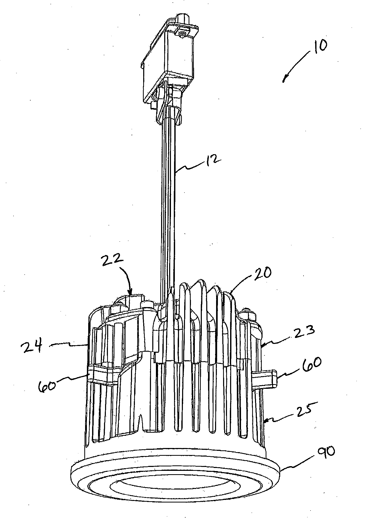
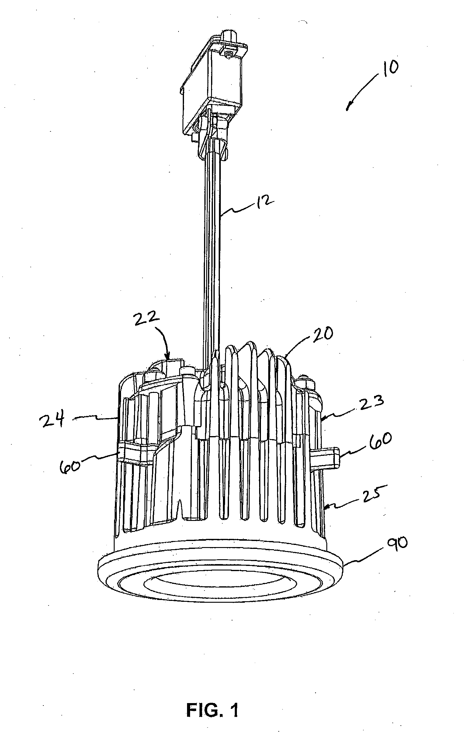
[0030]Turning initially to FIG. 1, a light fixture 10 according to one embodiment of the present invention includes a cable 12 for connecting to a network. The network may be either a standard network or a dedicated network for communication between a system controller (not shown) and individual light fixtures 10. Commands for controlling illumination of the light fixture 10, including but not limited to, the color or the brightness of the light fixture 10 may be transmitted over the network.

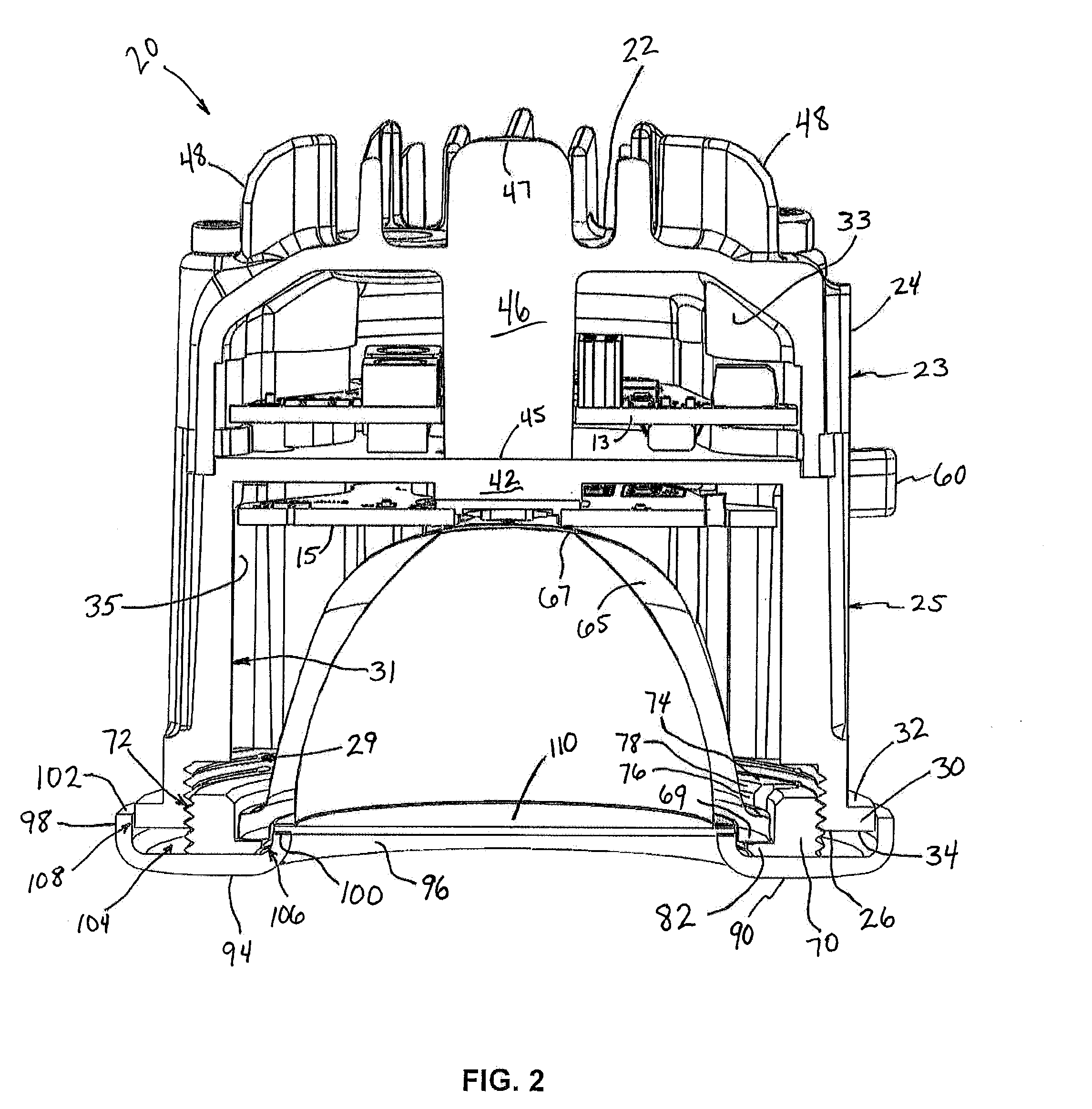
[0031]The light fixture 10 further includes a housing 20 having a rear wall 22 and at least one side wall 24 extending from the rear wall 22 to a front surface 26, shown in FIG. 2, of the housing 20. The side wall 24 may be a single wall forming a generally cylindrical housing or, altern...


PUM


Abstract

A housing for a recessed light fixture for installation into a passenger compartment of a vehicle includes a composite trim assembly. The composite trim assembly includes a spacer and a trim member. The spacer operably engages the housing of the light fixture and the trim member is connected to the spacer. The spacer aligns the trim member with the housing such that the trim member does not contact the housing. Consequently, the trim member, which is exposed to the passenger compartment upon installation, maintains a lower temperature than the housing to which it is connected.

Description

BACKGROUND OF THE INVENTION[0001]1. Field of the Invention[0002]The subject matter disclosed herein relates to a housing assembly for a recessed light. More specifically, a recessed housing for a light emitting diode (LED) light source used in a passenger cabin of a vehicle is disclosed.[0003]2. Discussion of the Related Art[0004]Conventional lighting systems for the passenger cabin of a vehicle, for example an airplane, are well known. Historically, these lighting systems have utilized fluorescent light to illuminate the cabin. However, fluorescent light fixtures require sufficient space to house the bulbs and the ballast required to regulate current through the bulbs. Further, the light fixture requires a certain amount of power to illuminate the bulb. Because vehicles, such as airplanes, have limited cabin space and a finite amount of power supplied by the on-board electrical system, it is desirable to provide lighting fixtures of smaller size with improved energy efficiency.[000...

Claims


Application Information

Patent Timeline
Patent Type & Authority Applications(United States)
IPC IPC(8): F21V29/00
CPCB64D2203/00F21S8/026F21Y2101/02F21V29/507B60Q3/0246B60Q3/0253B64D2011/0038B60Q3/0203B60Q3/41B60Q3/44B60Q3/51F21Y2115/10
Inventor WASNIEWSKI, CORYMAHAN, KYLE N.
Owner EMTEQ
Why Eureka
Try Eureka