3D Light Extraction System With Uniform Emission Across

a technology of light extraction and uniform emission, applied in the field of 3d light extraction system with uniform emission, can solve the problems of limited efficiency and utility of oled lighting panel, configuration such as shiang and d'andrade, and achieve the effect of improving illumination

Active Publication Date: 2012-06-28
UNIVERSAL DISPLAY
View PDF3 Cites 18 Cited by
  • Summary
  • Abstract
  • Description
  • Claims
  • Application Information

AI Technical Summary

Benefits of technology

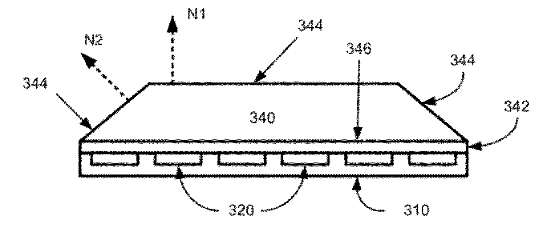
[0010]According to yet further aspects of the invention, a substantially 2-dimensional light source, such as an OLED emissive surface, may be converted to an apparently 3-dimensional light source. Systems and methods described herein may also be used to improve illumination away from a surface normal, as well as perform other functions, such as, hiding imperfections, mixing colors effectively, and / or disguising pixilation or shorted sub-pixels.

Problems solved by technology

An ongoing challenge for the OLED lighting industry is to improve the efficacy of OLED lighting panels through improved light extraction.
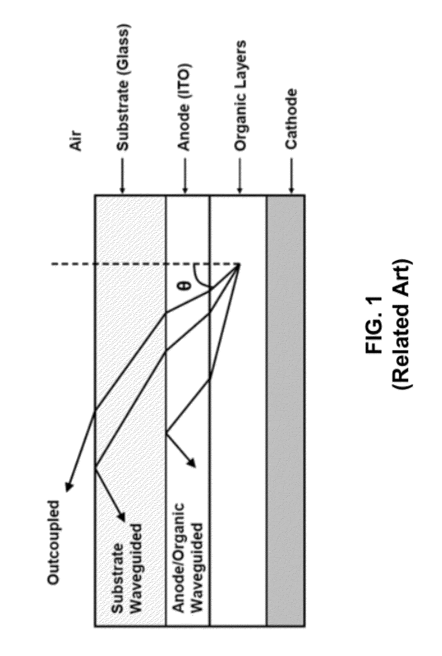
At the present time, OLED lighting panel efficacy is limited by light loss through waveguiding in the OLED stack.
Although the above techniques have proven to be somewhat more effective in terms of light extraction enhancement, they still suffer from a number of shortfalls that limit their efficiency and utility.
For example, configurations such as Shiang and D'Andrade do not provide uniform emission intensity and color across all viewing angles.
In this regard, Shiang is limited to an illumination from the front surface that lies parallel to the rear surface, and does not enhance any illumination away from the front surface normal.
D'Andrade also suffers from drawbacks in terms of uniform emission intensity and color with viewing angle, and exhibits a strong color shift with viewing angle, depending on which surface light is emitted from.

Method used


Image

  • 3D Light Extraction System With Uniform Emission Across
  • 3D Light Extraction System With Uniform Emission Across
  • 3D Light Extraction System With Uniform Emission Across

Examples


Embodiment Construction

[0052]It is understood that the invention is not limited to the particular methodology, protocols, and reagents, etc., described herein, as these may vary as the skilled artisan will recognize. It is also to be understood that the terminology used herein is used for the purpose of describing particular embodiments only, and is not intended to limit the scope of the invention. It also is be noted that as used herein and in the appended claims, the singular forms “a,”“an,” and “the” include the plural reference unless the context clearly dictates otherwise. Thus, for example, a reference to “a surface” is a reference to one or more surfaces and equivalents thereof known to those skilled in the art.

[0053]Unless defined otherwise, all technical and scientific terms used herein have the same meanings as commonly understood by one of ordinary skill in the art to which the invention pertains. The embodiments of the invention and the various features and advantageous details thereof are exp...


PUM

PropertyMeasurementUnit
heightaaaaaaaaaa
heightaaaaaaaaaa
heightaaaaaaaaaa

Abstract

Systems and methods for OLED lighting panels are provided in which a light extraction block is optically coupled to a light source. The light extraction block includes a plurality of non-parallel light emitting surface normals. At least one light diffusing layer covers a surface of the light extraction block. The light diffusing layer may be positioned, for example, on a light emitting surface of the light extraction block and/or on a mating surface of the light extraction block. The plurality of light emitting surface normals may be located on different non-parallel light emitting surfaces of the light extraction block, or on different points of a curved emitting surface. All of the light emitting surfaces and/or the mating surface, of the light extraction block may be covered by a light diffusing layer. The optical emission intensity and/or the optical emission color from the plurality of light emitting surface normals may be substantially equal.

Description

CROSS-REFERENCES TO RELATED APPLICATIONS[0001]This application is related to U.S. application Ser. No. ______, LIGHT EXTRACTION BLOCK WITH CURVED SURFACE; Attorney Docket Number 027166-006701US, filed contemporaneously herewith, the contents of which are hereby incorporated herein in their entirety.BACKGROUND OF THE INVENTION[0002]An ongoing challenge for the OLED lighting industry is to improve the efficacy of OLED lighting panels through improved light extraction. At the present time, OLED lighting panel efficacy is limited by light loss through waveguiding in the OLED stack. For example, in a typical planar bottom-emission OLED with no additional light extraction fixtures only as little as 20% of the generated photons can escape from the OLED stack and be emitted as useful illumination. The remaining photons are waveguided in the OLED stack.[0003]For example, FIG. 1 depicts a simplified ray diagram of a planar OLED demonstrating light loss through substrate and anode / organic laye...

Claims


Application Information

Patent Timeline
Patent Type & Authority Applications(United States)
IPC IPC(8): F21V11/00B23P11/00
CPCH01L2251/5361Y10T29/49826H01L51/5268H01L51/5275H10K50/854H10K50/858
Inventor LEVERMORE, PETER
Owner UNIVERSAL DISPLAY
Why Eureka
Try Eureka