Supercharge Your Innovation With Domain-Expert AI Agents!

Fluid flow channel scavenging system

a technology of flow channel and scavenging system, which is applied in the direction of filtration separation, carpet cleaning, separation process, etc., can solve the problems of not being able to achieve commercially viable solutions, and achieve the effect of minimizing reducing the potential for jamming, and economizing on the overall width

Active Publication Date: 2012-07-05
FRELIER CALVIN A
View PDF11 Cites 2 Cited by
  • Summary
  • Abstract
  • Description
  • Claims
  • Application Information

AI Technical Summary

Benefits of technology

[0002]In summary, this invention is a combination fluid flow channel and scavenging system to eject debris from the channel. This combination is configured to minimize the potential for jamming and economize on overall width. The channel includes a back wall, channel floor, and upward ramp extending forward to an outer lip. The scavenging system includes a pivoted actuator with a face plate on a framework adapted for reciprocating rolling contact between retracted and forward positions relative to the back wall. The scavenging system rolls on tracks as it traverses the channel. The channel profile and scavenging system are configured to maximize the angle between face plate and ramp surface thereby minimizing the potential for jamming of the scavenging system during operation while economizing on channel width. The outer lip includes a flat top surface for transient support of the face plate framework at the end of its forward movement. The scavenging system further includes flexible wiper blades for sequential wiping contact with debris as it traverses the channel, and a forward-extending slider blade spring-biased toward the channel.

Problems solved by technology

For example, U.S. Pat. No. 7,610,721 issued Nov. 3, 2009 shows a device although suitable for roof drainage systems where the debris is light but it falls short of commercially viable solution where debris is heavier in nature.

Method used


Image

  • Fluid flow channel scavenging system
  • Fluid flow channel scavenging system
  • Fluid flow channel scavenging system

Examples


Embodiment Construction

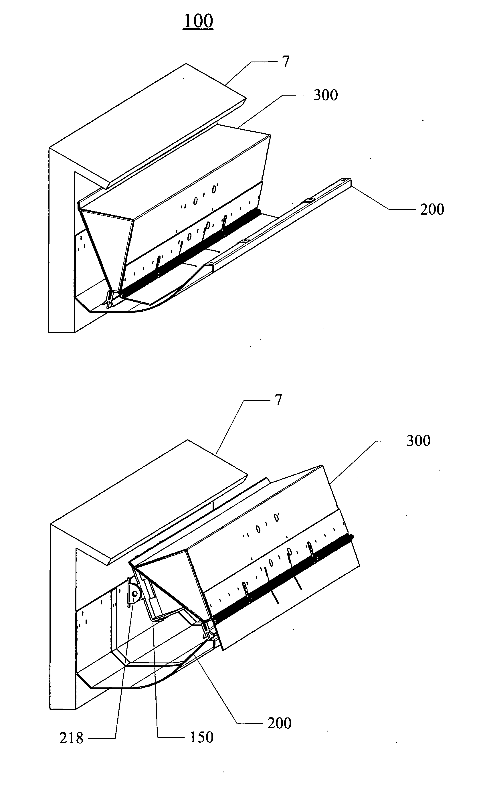
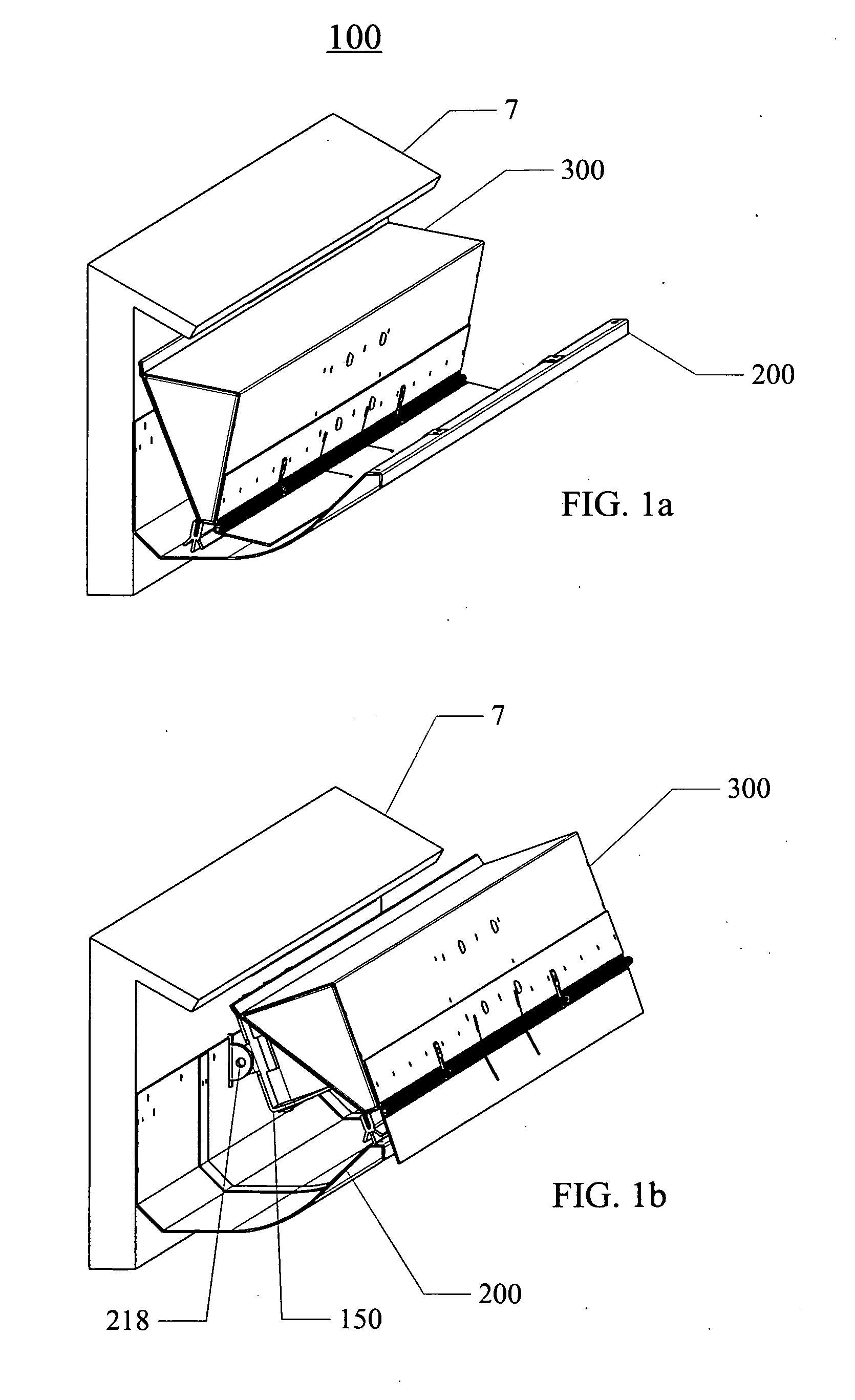
[0020]With reference now to the drawing figures: FIG. 1 show a combination fluid flow channel and scavenging system 100 (hereinafter referred to as system 100) mounted to structure 7 under the edge of a sloped roof surface with scavenger assembly 300 in the retracted or park position. System 100 allows fluid to flow along its length with the capability to expel accumulated solids in a direction roughly perpendicular to its length. Fluid flow systems tend to collect debris in the fluid flow channel; reliable function requires debris removal to promote drainage. FIG. 1b shows system 100 mounted to structure 7 with scavenger assembly 300 in the forward position after debris expulsion resting on fluid flow channel 200. It also shows actuator 150 (prior art defined in U.S. Pat. No. 7,610,721) attached to hinge clip 218 with a shaft (not shown).

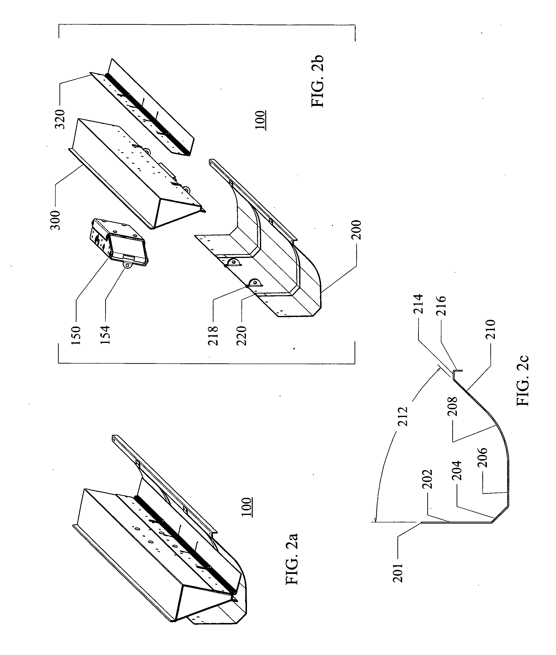
[0021]FIG. 2a shows system 100 separate from supporting structure. FIG. 2b is an exploded view of system 100 that shows actuator 150 (prior art U....


PUM

PropertyMeasurementUnit
angleaaaaaaaaaa
torqueaaaaaaaaaa
resistance angleaaaaaaaaaa

Abstract

A fluid flow channel includes a scavenging system to eject debris from the channel. The channel includes a back wall, channel floor, and upward ramp extending forward to an outer lip. The scavenging system includes a pivoted actuator with a face plate on a framework adapted for reciprocating rolling contact between retracted and forward positions relative to the back wall. The scavenging system rolls on tracks as it traverses the channel. The channel profile and scavenging system are configured to maximize the angle between face plate and ramp surface thereby minimizing the potential for jamming of the scavenging system during operation while economizing on channel width. The outer lip includes a flat top surface for transient support of the face plate framework at the end of its forward movement. The scavenging system further includes flexible wiper blades for sequential wiping contact with debris as it traverses the channel, and a forward-extending slider blade spring-biased toward the channel.

Description

BACKGROUND INFORMATION[0001]Mechanically Actuated Self Cleaning Fluid Drainage System needs to be both commercially viable and robust in environments that contain heavy debris and grit accumulation associated with decaying roof drainage systems. For example, U.S. Pat. No. 7,610,721 issued Nov. 3, 2009 shows a device although suitable for roof drainage systems where the debris is light but it falls short of commercially viable solution where debris is heavier in nature. There is therefore a need for an improved Mechanically Actuated Self Cleaning Fluid Drainage System.SUMMARY OF THE INVENTION[0002]In summary, this invention is a combination fluid flow channel and scavenging system to eject debris from the channel. This combination is configured to minimize the potential for jamming and economize on overall width. The channel includes a back wall, channel floor, and upward ramp extending forward to an outer lip. The scavenging system includes a pivoted actuator with a face plate on a ...

Claims


Application Information

Patent Timeline
Patent Type & Authority Applications(United States)
IPC IPC(8): B01D21/30
CPCE04D13/0765B08B9/00
Inventor FRELIER, CALVIN A.
Owner FRELIER CALVIN A
Features
  • R&D
  • Intellectual Property
  • Life Sciences
  • Materials
  • Tech Scout
  • Unparalleled Data Quality
  • Higher Quality Content
  • 60% Fewer Hallucinations
Learn More