Fuel filter of an internal combustion engine

Active Publication Date: 2012-07-05
HENGST WALTER
View PDF3 Cites 2 Cited by
  • Summary
  • Abstract
  • Description
  • Claims
  • Application Information

AI Technical Summary

Benefits of technology

[0005]The present invention accordingly has the object of providing a fuel filter of the initially indicated type which avoids the aforementioned disadvantages and in which in particular a favorable arrangement of the raw fuel inlet is rendered possible and in which the separation of water droplets from the fuel is encouraged.

Problems solved by technology

It is to be considered disadvantageous with this known fuel filter that the separation of water droplets entrained in the fuel is rendered more difficult due to the flow of the fuel to be cleaned from the bottom to the top at the outer circumference of the filter insert.
In this case, fuel disadvantageously always remains in the cup which may easily result in pollution and renders it difficult to change the filter insert.

Method used


Image

  • Fuel filter of an internal combustion engine
  • Fuel filter of an internal combustion engine
  • Fuel filter of an internal combustion engine

Examples


Embodiment Construction

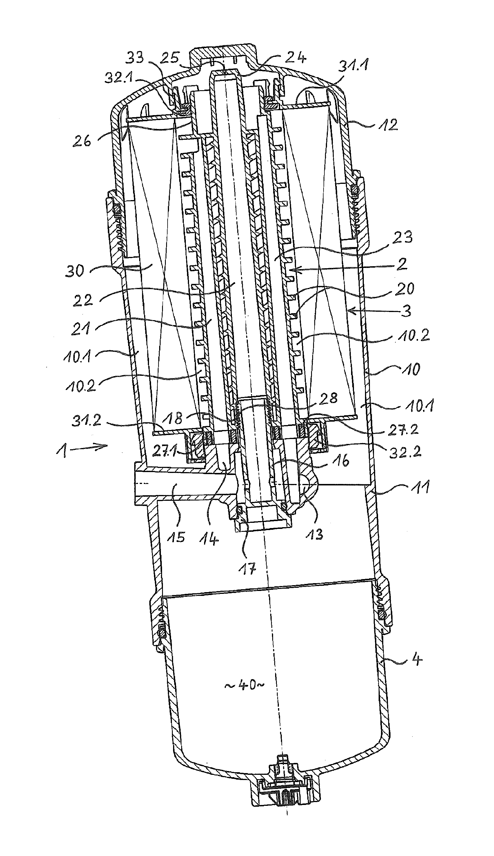
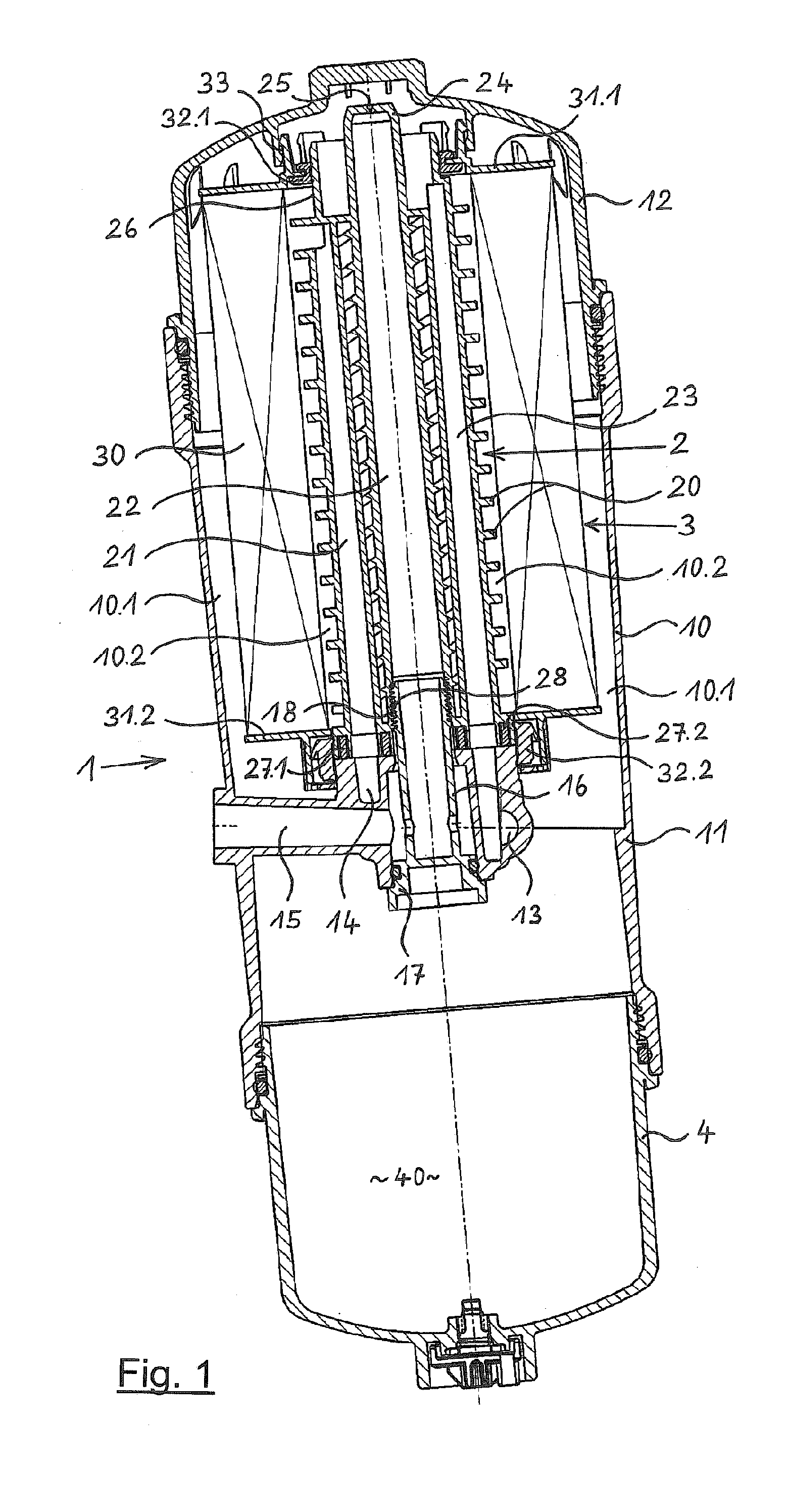
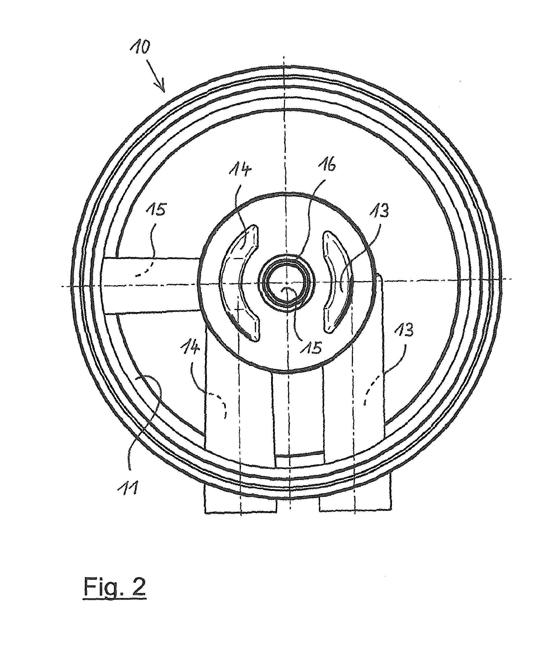
[0027]FIG. 1 shows a fuel filter 1 in longitudinal section. The fuel filter 1 has a filter housing 10 with a housing base 11 and a topside housing cover 12. A ring filter insert 3 is arranged in the filter housing 10. On the inside of the ring filter insert 3, a support body 2 is provided which is connected on its bottom end with the housing base 11, here screwed. The lowermost part of the filter housing 10 is formed by a water collection cup 4 forming a water collection chamber 40.

[0028]On its outer circumference, the support body 2 has a plurality of support ribs 20 protecting a filter media body 30 of the ring filter insert 3 from collapsing. Altogether three flow channels 21, 22 and 23 extend on the inside of the support body 2. The first flow channel 21 is used to pass pure fuel from a pure area 10.2 of the housing 10 to a pure fuel outlet 14. The second flow channel 22 in the center of the support body 2 is used to vent the filter housing 10. To this end, the upper end 24 of t...


PUM

PropertyMeasurementUnit
Forceaaaaaaaaaa
Flow rateaaaaaaaaaa
Areaaaaaaaaaaa

Abstract

A fuel filter of an internal combustion engine including a filter housing having a lowermost housing base and a topmost removable housing lid. The filter housing has one raw fuel inlet and one pure fuel outlet. A replaceable annular filter insert mounts there in the filter housing, fuel flowing through it from outside towards inside. The filter subdivides an interior space of the filter housing into a raw zone and a pure zone. A supporting body is arranged in the interior of the annular filter insert, a first flow channel and a second flow channel extending therethrough. The first flow channel connects at one end to the pure zone and at the other end to the pure fuel outlet. The second flow channel connects at one end to the raw zone via a vent throttle or a vent valve and at the other end to a reservoir return in the filter housing. The raw fuel inlet is in the housing base and a flow channel leads from the raw fuel inlet to a portion of the raw zone of the interior space of the filter housing which is, during operation, topmost.

Description

BACKGROUND OF THE INVENTION[0001]This invention relates to a fuel filter of an internal combustion engine, in particular of a diesel engine, with a filter housing having an operationally lower housing base and an upper, removable housing cover, with one raw fuel inlet and pure fuel outlet each being provided in the filter housing, with a replaceable ring filter insert being arranged in the filter housing through which the fuel can flow radially from the outside to the inside, said ring filter insert subdividing an interior of the filter housing into a raw area and a pure area, with a support body being arranged in the interior of the ring filter insert through which extends a first flow channel being connected, on the one hand, with the pure area and, on the other hand, with the pure fuel outlet, and a second flow channel being connected, on the one hand, with the raw area via a vent throttle or a vent valve and, on the other hand, with a tank return in the filter housing.[0002]A fu...

Claims


Application Information

Patent Timeline
IPC IPC(8): F02M37/22B01D35/30B01D35/01F02M37/28F02M37/42F02M37/54
CPCB01D2201/0415B01D2201/34B01D36/001F02M37/221B01D2201/291B01D2201/305B01D36/003F02M37/28F02M37/54F02M37/42
Inventor HOLKER, JURGENVINKELAU, CHRISTIAN
Owner HENGST WALTER
Why Eureka
Try Eureka