Liquid crystal display

Active Publication Date: 2016-06-07
BEIJING BOE OPTOELECTRONCIS TECH CO LTD
View PDF20 Cites 0 Cited by
  • Summary
  • Abstract
  • Description
  • Claims
  • Application Information

AI Technical Summary

Benefits of technology

[0008]In the liquid crystal display according to the present invention, the electrode is formed between the edge portion of the effective display region of the array substrate and the sealant, and the electrode is connected to the first DC power, so that an electric field and thus a voltage difference are forme

Problems solved by technology

During the above described cell assembling process, if the sealant comes into contact with the liquid crystal before completely cured, the liquid crystal will be polluted.
The display quality of the polluted liquid crystal display panel may deteriorate dramatically.
Image sticking, especially, line image sticking is liable to occur, especially around the effective display a

Method used


Image

  • Liquid crystal display
  • Liquid crystal display
  • Liquid crystal display

Examples


Example

[0016]Hereinafter, a liquid crystal display according to embodiments of the present invention will be described in detail with reference to the accompanying drawings.

[0017]It is clear that the described embodiments are only a part of embodiments of the present invention, not all embodiments of the present invention. Based on the embodiments of the present invention, those skilled in the art can obtain all other embodiments within the scope of the present invention without any labor of creativity.

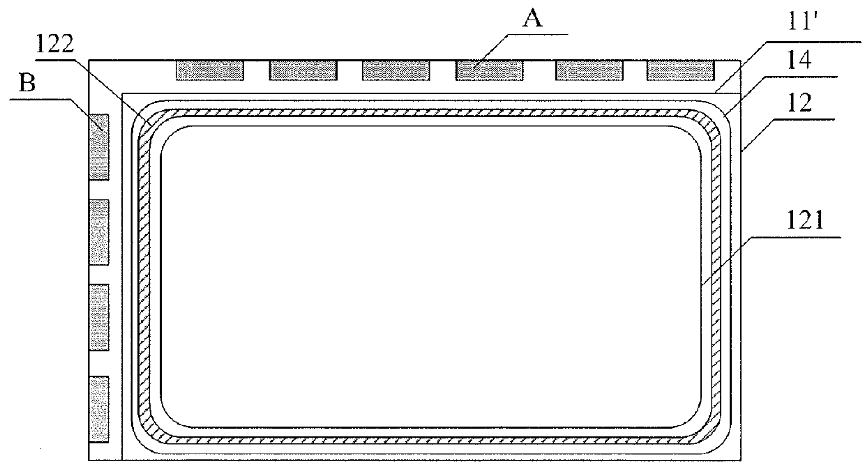
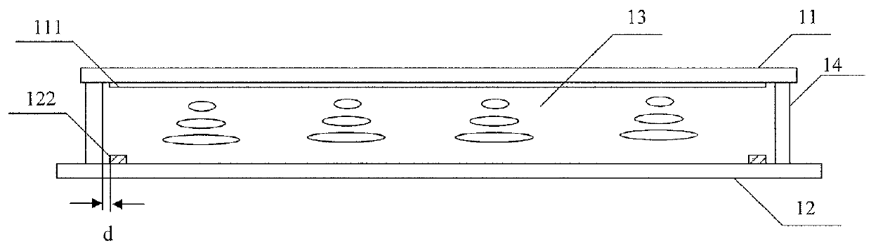
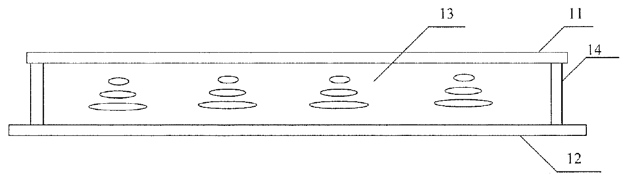
[0018]As shown in FIG. 2, a liquid crystal display of the present invention comprises a color filter substrate 11 and an array substrate 12, which are assembled together with a sealant 14, and a metal electrode 122 formed between an edge portion of an effective display region of the array substrate 12 and the sealant 14. The metal electrode 122 is connected to a first DC power (not shown in drawings). A common electrode 111 is disposed on the color filter substrate 11 above the metal electro...


PUM


Abstract

The embodiments of the present invention disclose a liquid crystal display. The liquid crystal display comprises: a color filter substrate and an array substrate assembled together with a sealant, wherein an electrode is formed between an edge portion of an effective display region of the array substrate and the sealant, and the metal electrode is connected to a first DC power.

Description

BACKGROUND[0001]The present invention relates to a liquid crystal display (LCD).[0002]Liquid crystal displays (LCDs) have a lot of advantages. For example, compared with a cathode ray tube, liquid crystal displays are thinner and have lower energy consumption. Therefore, liquid crystal displays have substituted CRT displays in many fields.[0003]As shown in FIG. 1, a display panel of an existing thin film transistor-liquid crystal display (TFT-LCD) includes an array substrate 12, a color filter substrate 11, and a liquid crystal layer 13 interposed between the array substrate 12 and the color filter substrate 11. The peripheries of the array substrate 12 and the color filter substrate 11 are sealed with a sealant 14. FIG. 1 does not show all configurations of the liquid crystal display for the sake of brevity.[0004]In an existing process of manufacturing a liquid crystal display, after the processes of forming the array substrate and the color filter substrate, it requires to perform...

Claims


Application Information

Patent Timeline
IPC IPC(8): G02F1/1345G02F1/1339
CPCG02F1/1339
Inventor MA, XINLIKIM, HEECHEOLRYU, JAI-IL
Owner BEIJING BOE OPTOELECTRONCIS TECH CO LTD
Why Eureka
Try Eureka