Laundry Device
- Summary
- Abstract
- Description
- Claims
- Application Information
AI Technical Summary
Benefits of technology
Problems solved by technology
Method used
Image
Examples
first embodiment
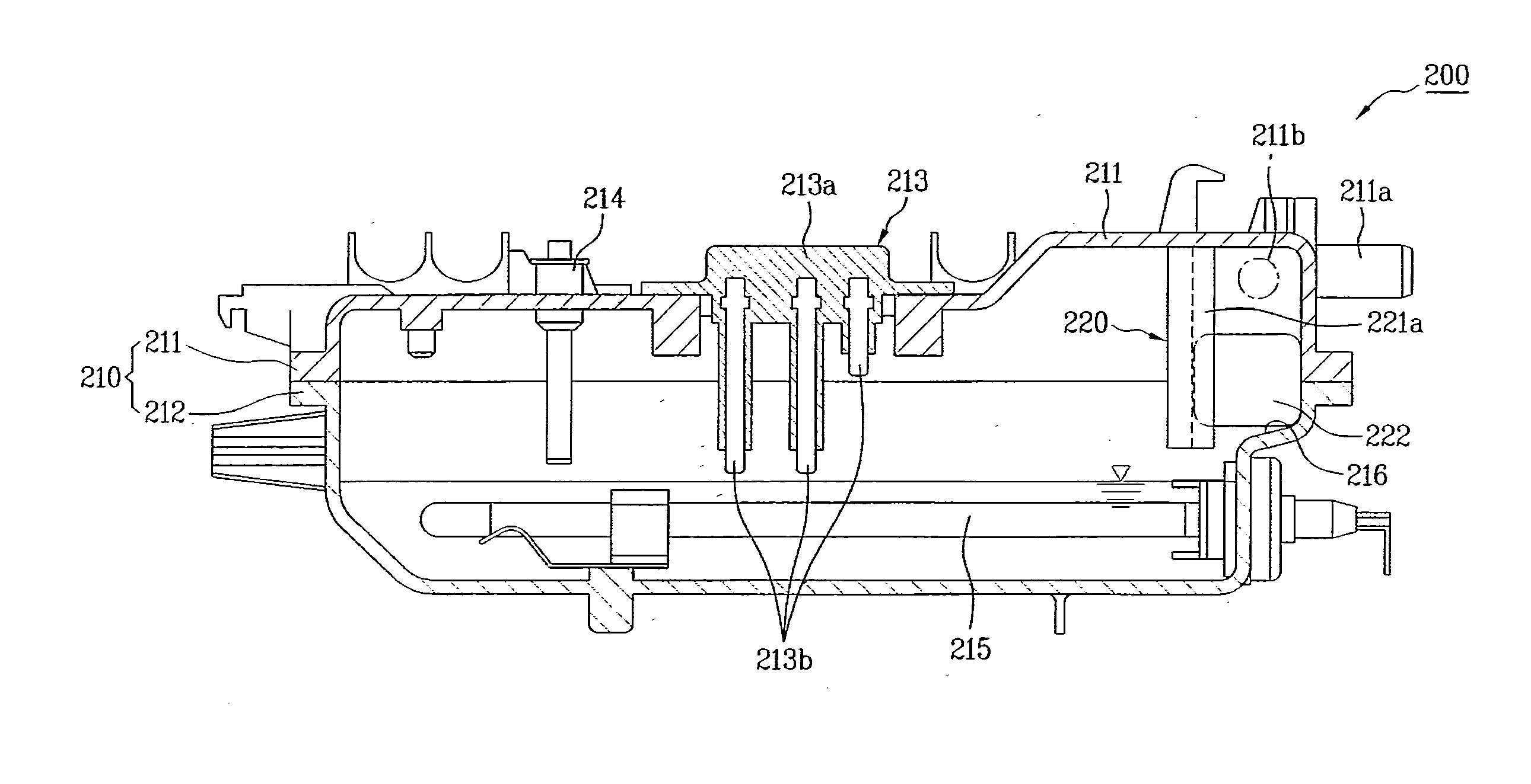
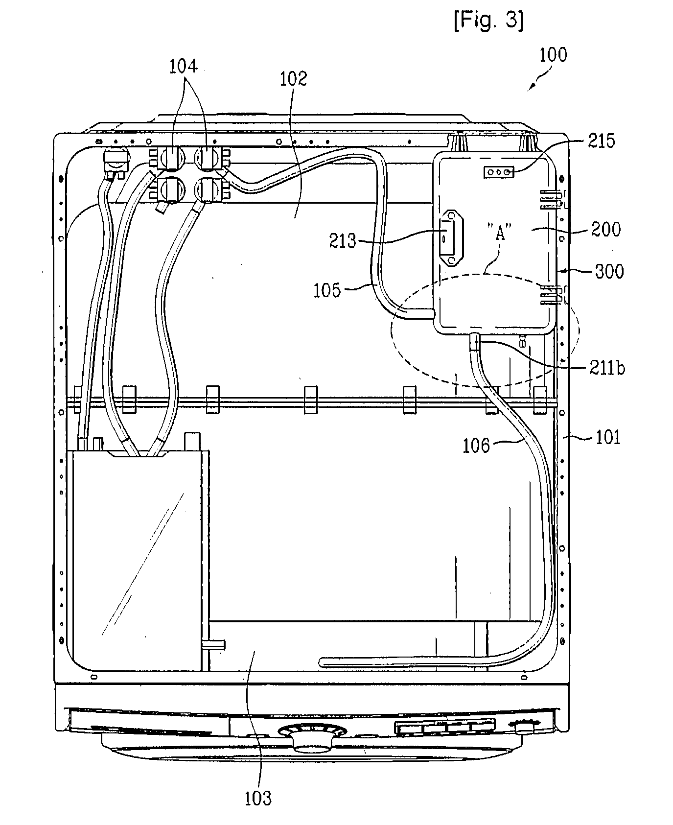
[0057]Hereinafter, with reference to FIGS. 3 to 5, a steam generator for a laundry device in accordance with the present invention will be described.
[0058]As shown in FIG. 3, the steam generator 200 of the first embodiment, to which a water supply pipe 105 and a steam supply pipe 106 are connected, is installed in a cabinet 101 of a drum washing machine 100.
[0059]Preferably, the steam generator 200 is installed above the tub 102 so that a channel connected between the water supply valve 104 and the steam supply pipe 106 has a relatively short distance and the steam generator 200 is easily repaired and inspected.
[0060]The steam generator 200 comprises a case 210 and a water oversupply prevention unit 220.
[0061]The case 210 forms the external appearance of the steam generator 200, and stores water supplied from the water supply valve 104.
[0062]Preferably, the case 210 includes an upper case 211 forming the upper portion of the steam generator 200, and a lower case 212 forming the lowe...
second embodiment
[0100]Hereinafter, with reference to FIGS. 6 and 7, a steam generator in accordance with the present invention will be described.
[0101]For the reference, parts of the steam generator of the second embodiment are substantially the same as those in the first embodiment except for a water oversupply prevention unit. The parts of the steam generator of the second embodiment, which are substantially the same as those in the first embodiment, are denoted by the same reference numerals even through they are depicted in different drawings, and a detailed description thereof will thus be omitted because it is considered to be unnecessary.
[0102]Now, the water oversupply prevention unit installed in the steam generator of the second embodiment will be described.
[0103]As shown in FIG. 6, the water oversupply prevention unit 320 comprises a switching member 321 for opening and closing the water supply hole 211a, a hinge 322 installed at one side of the inner surface of the case 210, and a floate...
third embodiment
[0115]Hereinafter, with reference to FIGS. 8 and 9, a steam generator in accordance with the present invention will be described.
[0116]For the reference, parts of the steam generator of the third embodiment, which are substantially the same as those in the first and second embodiments, are denoted by the same reference numerals even through they are depicted in different drawings, and a detailed description thereof will thus be omitted because it is considered to be unnecessary.
[0117]The steam generator 200 comprises the case 210 containing water and provided with the water supply hole 211a connected to the water supply pipe 105 and the discharge hole 211b connected to the steam supply pipe 106, the heater 215 for heating the water, and a backflow prevention unit 230.
[0118]The backflow prevention unit 230 prevents steam generated from the case 210 from leaking toward the water supply valve 104.
[0119]Preferably, the backflow prevention unit 230 is a check valve for causing the water ...
PUM
 Abstract
Description
Claims
Application Information
 - R&D
- Intellectual Property
- Life Sciences
- Materials
- Tech Scout
- Unparalleled Data Quality
- Higher Quality Content
- 60% Fewer Hallucinations
Browse by: Latest US Patents, China's latest patents, Technical Efficacy Thesaurus, Application Domain, Technology Topic, Popular Technical Reports.
© 2025 PatSnap. All rights reserved.Legal|Privacy policy|Modern Slavery Act Transparency Statement|Sitemap|About US| Contact US: help@patsnap.com


