Method And Apparatus For Detecting A Plugged Nozzle Of A Sprayer

a sprayer and nozzle technology, applied in the field of farm implements, can solve the problems of difficult, if not impossible, and difficult to achieve the fan angle, pattern and coverage width, and achieve the effect of double the application of chemical solutions, and increased fuel costs of the tractor

a sprayer and nozzle technology, applied in the field of farm implements, can solve the problems of difficult, if not impossible, and difficult to achieve the fan angle, pattern and coverage width, and achieve the effect of double the application of chemical solutions, and increased fuel costs of the tractor

US20120168530A1Inactive Publication Date: 2012-07-05BLUE LEAF I P INC

Image

  • Method And Apparatus For Detecting A Plugged Nozzle Of A Sprayer
  • Method And Apparatus For Detecting A Plugged Nozzle Of A Sprayer
  • Method And Apparatus For Detecting A Plugged Nozzle Of A Sprayer

Examples


Embodiment Construction

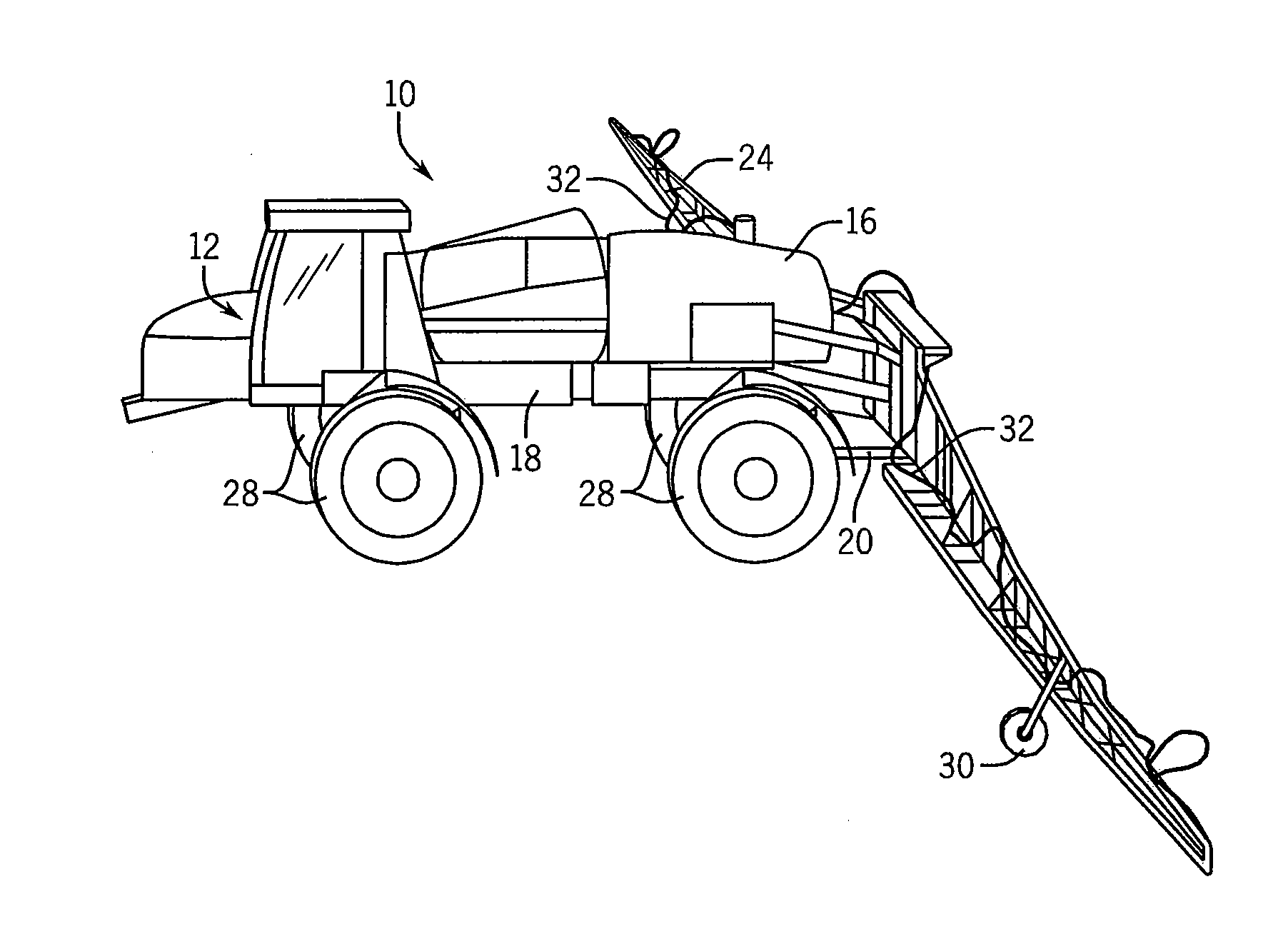
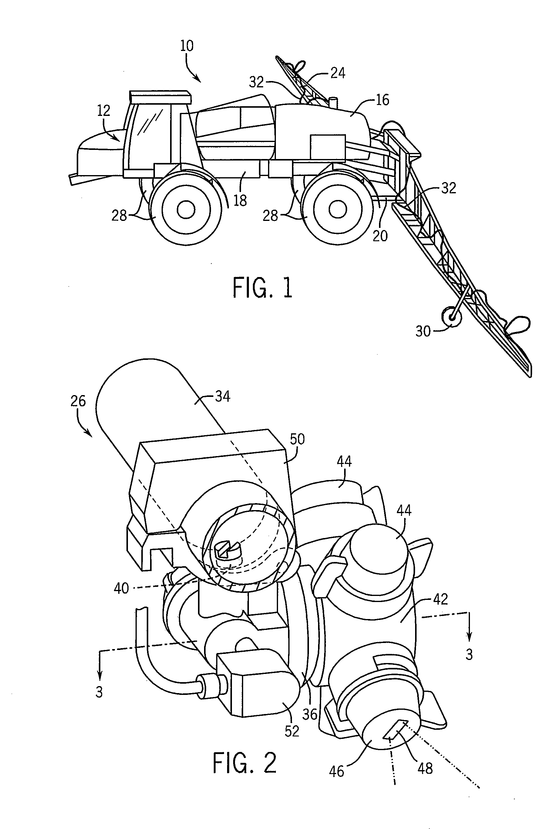
[0017]FIG. 1 shows an agricultural product application system, which in the illustrated embodiment, is a field spraying system 10 comprised of a self-propelled sprayer 12 having a fluid tank 16 that is supported by a chassis 18 in a known manner. As also known in the art, a rear end 20 of the chassis 18 supports a pair of wing booms 22, 24 to which a series of spray nozzle assemblies 26 are coupled. An exemplary spray nozzle assembly 26 is shown in FIG. 2. The chassis is supported by a set of tires 28 and the wing booms are supported by smaller wheels 30. As known in the art, distribution lines 32 are flow coupled to the fluid tank 16 in a conventional manner, which allows fluid, e.g., fluidized fertilizer, pesticide, herbicide, etc., to be passed to a header 34, FIG. 2, to which the spray nozzle assemblies 26 are coupled.

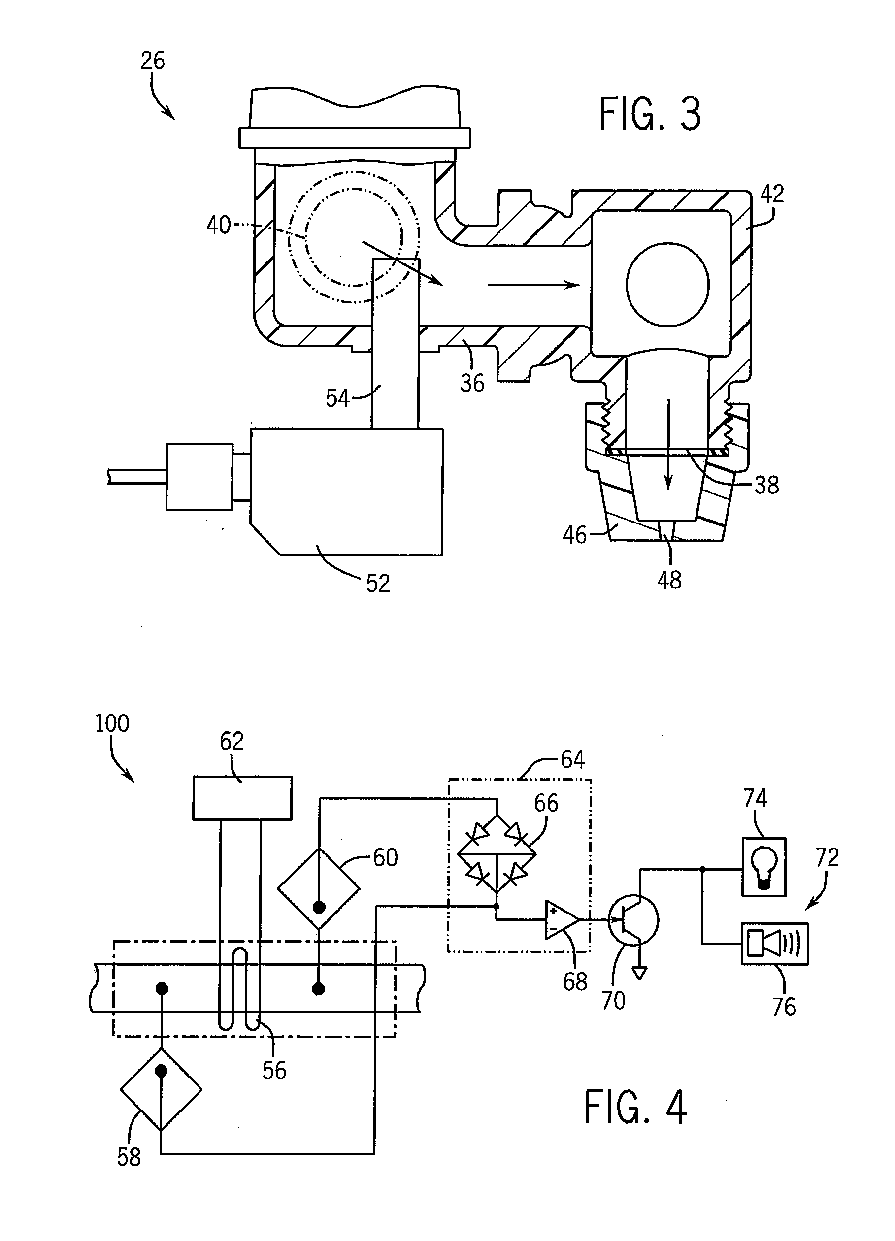
[0018]Referring now to FIGS. 2 and 3, an exemplary spray nozzle assembly 26 has a nozzle body 36 fluidly interconnected between five (5) fluid outlet ports 38 and ...


PUM


Abstract

A plugged nozzle monitoring system uses a thermal flow sensor located within a spray nozzle of an agricultural sprayer. The thermal flow sensor is free of moving parts and is made of corrosion-resistant materials. The thermal flow sensor is placed within the fluid flow path through the nozzle and activates an alarm if flow through the nozzle falls below the baseline value.

Description

BACKGROUND OF THE INVENTION[0001]The present invention is directed to farm implements and, more particularly, to a plugged nozzle warning system for use with a sprayer of a farm implement.[0002]Field sprayers, as known in the art, are typically towed by a tractor or other towing vehicle and include a fluid holding tank supported by a frame and fluidly coupled to a series of spray nozzles equidistantly spaced from one another along booms extending outwardly from the frame. Crop protection fluid, such as pesticides, or liquid fertilizer are dispensed through the spray nozzles onto the farm field and preferably in an even distribution spray patter so that the fluid is applied consistently across the farm field.[0003]When spraying, or otherwise depositing, fluids onto the farm field, it is important that the spray nozzles are unclogged. If one or more of the nozzles is fully, or partially, clogged, the intended fan angle, pattern, and coverage width will be difficult, if not impossible,...

Claims


Application Information

Patent Timeline
05 Jul 2012
Publication
US20120168530A1
IPC
B67D7/08
CPC
B05B1/202; A01C23/007; B05B12/008
Inventors
ELLINGSON, JON; TOLLEFSRUD, AARON