Process for the preparation of conformable materials for downhole screens

Active Publication Date: 2012-07-05
BAKER HUGHES INC
View PDF2 Cites 35 Cited by
  • Summary
  • Abstract
  • Description
  • Claims
  • Application Information

AI Technical Summary

Benefits of technology

[0007]The present invention relates to a method of controlling the microcellular structure in conformable materials, comprising a foamed polymer composition, by varying the quality of component mixing during manufacture of the material.

Problems solved by technology

Problems arose with the screen expansion technique as a replacement for gravel packing because of wellbore shape irregularities.
However, controlling a foaming process has been difficult and unpredictable.

Method used


Image

  • Process for the preparation of conformable materials for downhole screens
  • Process for the preparation of conformable materials for downhole screens
  • Process for the preparation of conformable materials for downhole screens

Examples


example 1

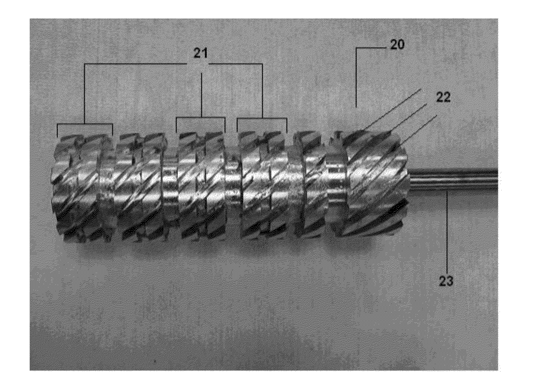
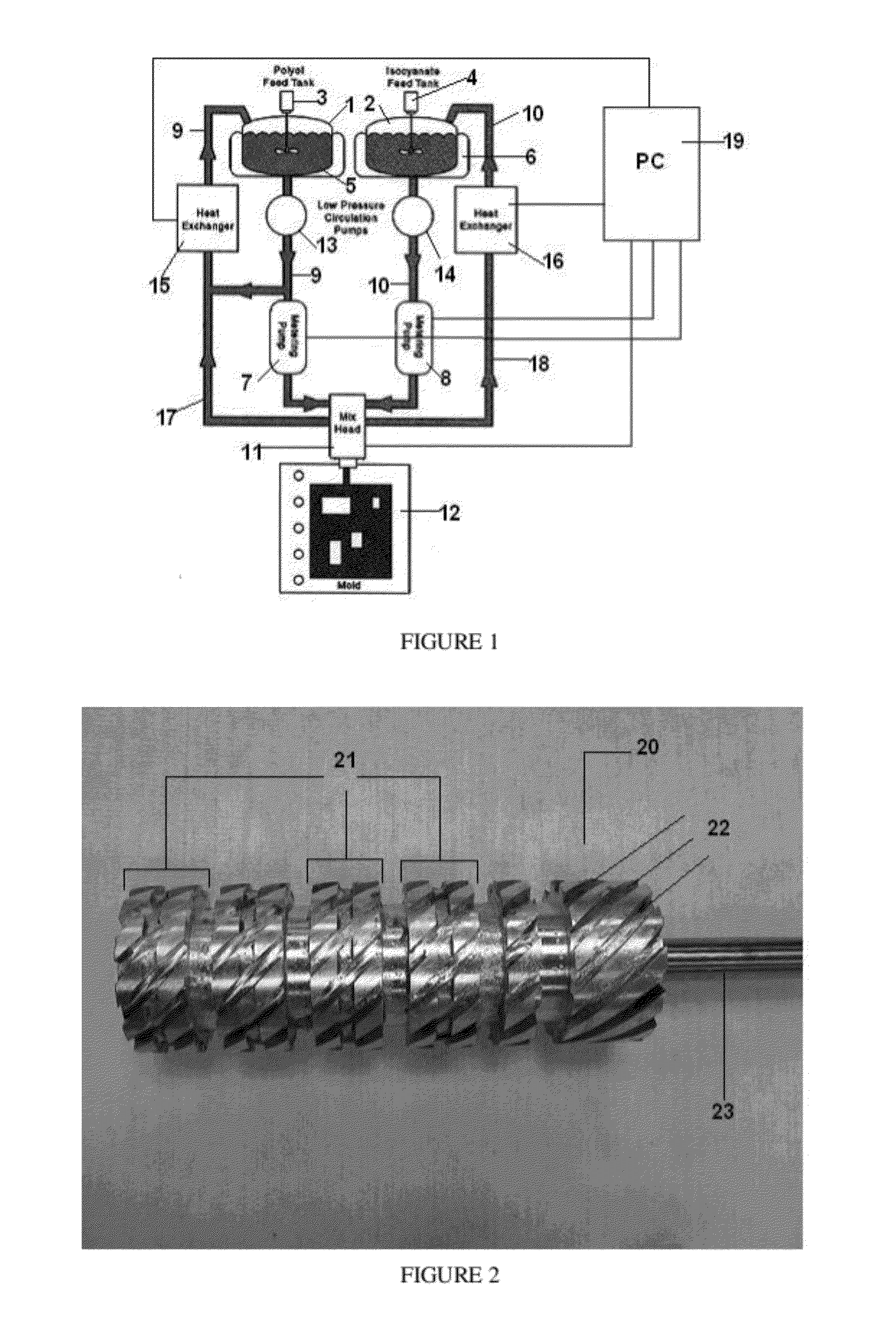
[0087]This Example demonstrates how cell size is affected by a rotary mixing head, as characterized by mixing quality. A rotary shearing type mixer, as shown in FIG. 2, was used in a reaction injection molding process such as shown in FIG. 1. The mixing quality was varied from 14.4 cuts / g to 135 cuts / g. The cell size was found to be affected by the mixing quality. The effect of this is seen in the FIGS. 3(a), 3(b), 4(a), and 4(b), and the accompanying Table 1 below.

TABLE 1IsocyanatePolyolMixingComponentComponentparameter,Cell size,Example° F.° F.cuts / gmm1a8417314.42.31b8417227.01.81c8516845.01.61d8517599.00.841e861691350.97

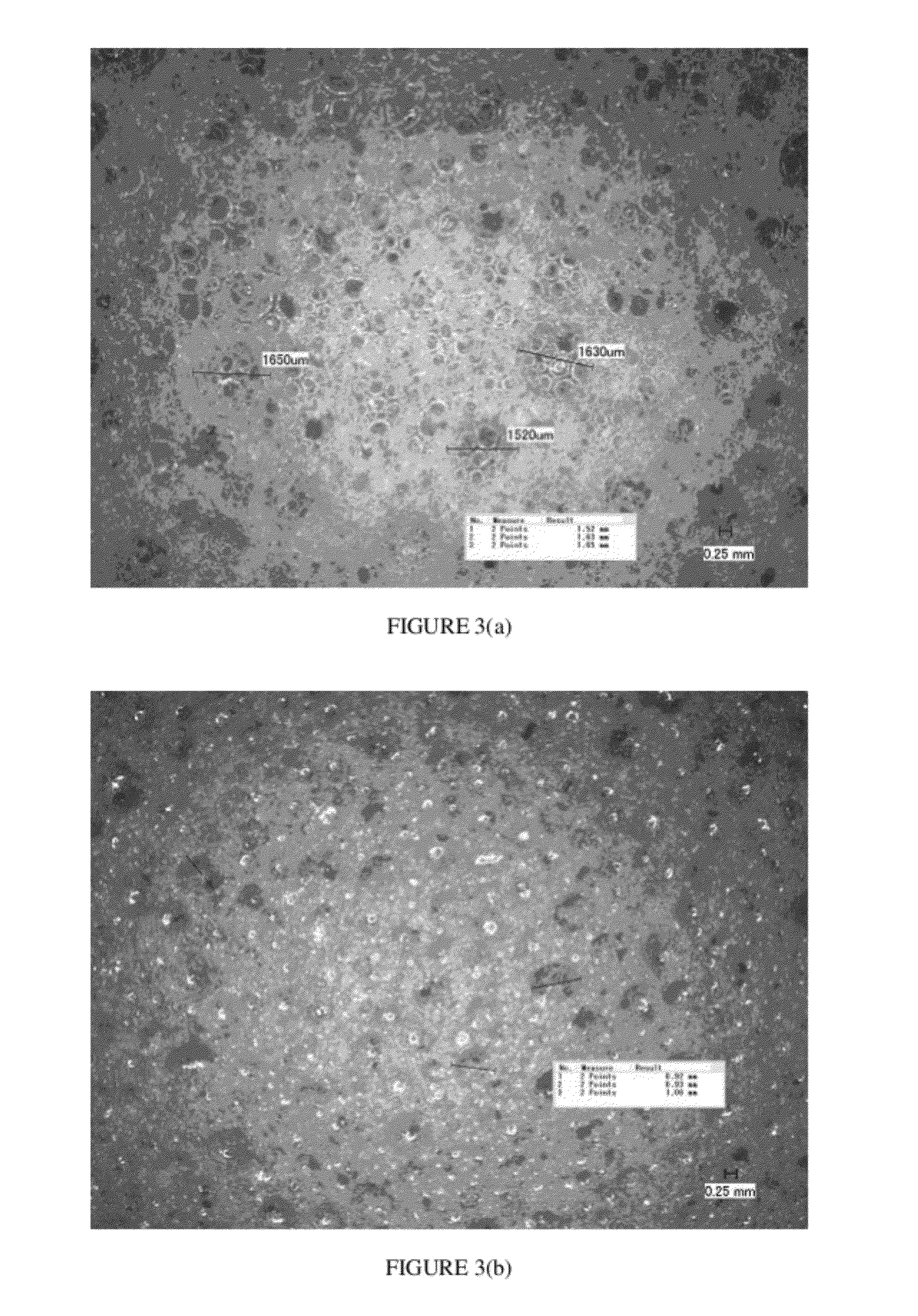
[0088]Similarly, FIGS. 3(a) and 3(b) show images of foamed conformable materials made in which the quality of mixing was varied from 45 cuts / g to 99 cuts / g, respectively, corresponding to Examples 1c and 1d in Table 1.

[0089]FIG. 4(a) shows a graph of cell size in the resulting product versus polyol temperature for a reaction mixture used in a process according to ...

example 2

[0091]This Example demonstrates how the cell size for a foamed conformable material is affected by quality of mixing in an injection molding process in which an impingement mixing is employed. A reaction injection molding process such as shown in FIG. 1 was carried out using an impingement mixing head in which the mixing quality was varied. The results are shown in Table 2 below.

[0092]In the case of jet impingement mixing, the quality of mixing was controlled based on the injection rate of one of the components when the injection rate of the second component must be selected to provide the stoichiometric ratio. The results are shown in Table 2.

TABLE 2IsocyanatePolyolMixingMixingPressureComponentComponentparameterparameterExamplepsig / sg / sIsoPolyCell size2a10004485002.21.9Very large2b100089510008.97.8Very small2c1000134315002018Very small

[0093]As shown by the results in Table 2, the cell size was found to be affected by the mixing quality. As the injection rate of polyol increases fro...


PUM

PropertyMeasurementUnit
Temperatureaaaaaaaaaa
Sizeaaaaaaaaaa

Abstract

A process of making a foamed conformable material by reaction injection molding comprises providing a first component from a first feed tank at a first flow rate, via a first conduit, to a mixing device; providing a second component from a second feed tank at a second flow rate, via a second conduit, to the mixing device, the second component reactive with the first component in the presence of a foaming agent; mixing the first component and the second component in the mixing device to form a reaction mixture; introducing the reaction mixture into an injection molding device; molding the reaction mixture to form a foamed conformable material; wherein the mixing of the reaction mixture is adjusted to achieve a desired average cell size of the foamed conformable material. The process can produce wellbore-conforming materials that can function to filter out sand or other undesirable fines from a formation.

Description

FIELD OF THE INVENTION[0001]The field of this invention relates to materials for downhole screens and, more particularly, materials that can be expanded to fill the annular gap in a regularly or irregularly shaped borehole. The material is foamed to obtain a preselected cell size to facilitate screened production flow through the conformable material.BACKGROUND OF THE INVENTION[0002]Various methods of wellbore isolation, screen filtration, and production control are known in the art, including applications in the field of oil and gas exploitation. In the past, the annular space in a borehole, outside the screen of a tubing string, was filled with gravel to prevent the production of undesirable sand and other fines from a formation. More recently, with the advent of tubular expansion technology, it was thought that the need for gravel packing could be eliminated if the screen could be expanded in place to eliminate the surrounding annular space that had heretofore been packed with gr...

Claims


Application Information

Patent Timeline
IPC IPC(8): C08J9/12
CPCB01F7/00816B29B7/407B29B7/7404E21B43/103C08J2375/04E21B43/08B29C44/3442B29B7/401B29B7/404B01F27/2722B29B7/7615B29B7/7647B29B7/7414B29B7/7419B29B7/826B29B7/823B29B7/728E21B43/108B29B7/603
Inventor MAZYAR, OLEG A.JOHNSON, MICHAEL H.GUEST, RANDALL V.
Owner BAKER HUGHES INC
Why Eureka
Try Eureka