Braking system for motor vehicles and method for operating the same

a technology for braking systems and motor vehicles, applied in braking systems, vehicle components, foot actuation initiations, etc., can solve problems such as brake failure and considerable lengthening of the travel of the brake pedal

Active Publication Date: 2012-07-05
CONTINENTAL TEVES AG & CO OHG
View PDF6 Cites 71 Cited by
  • Summary
  • Abstract
  • Description
  • Claims
  • Application Information

AI Technical Summary

Benefits of technology

[0012]It is therefore an object of the present invention to improve a brake system of the type specified above such that a failure of

Problems solved by technology

It is considered to be a severe disadvantage of that known brake system that, in the event of a failure of the electric drive of the electrohydraulic pressure generating device during a

Method used


Image

  • Braking system for motor vehicles and method for operating the same
  • Braking system for motor vehicles and method for operating the same

Examples


Embodiment Construction

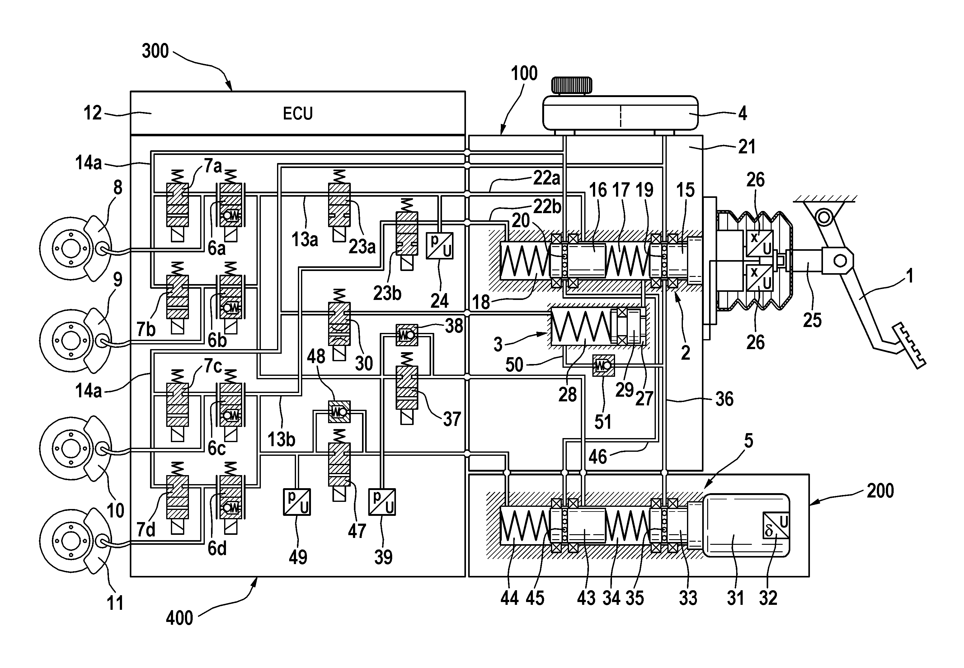
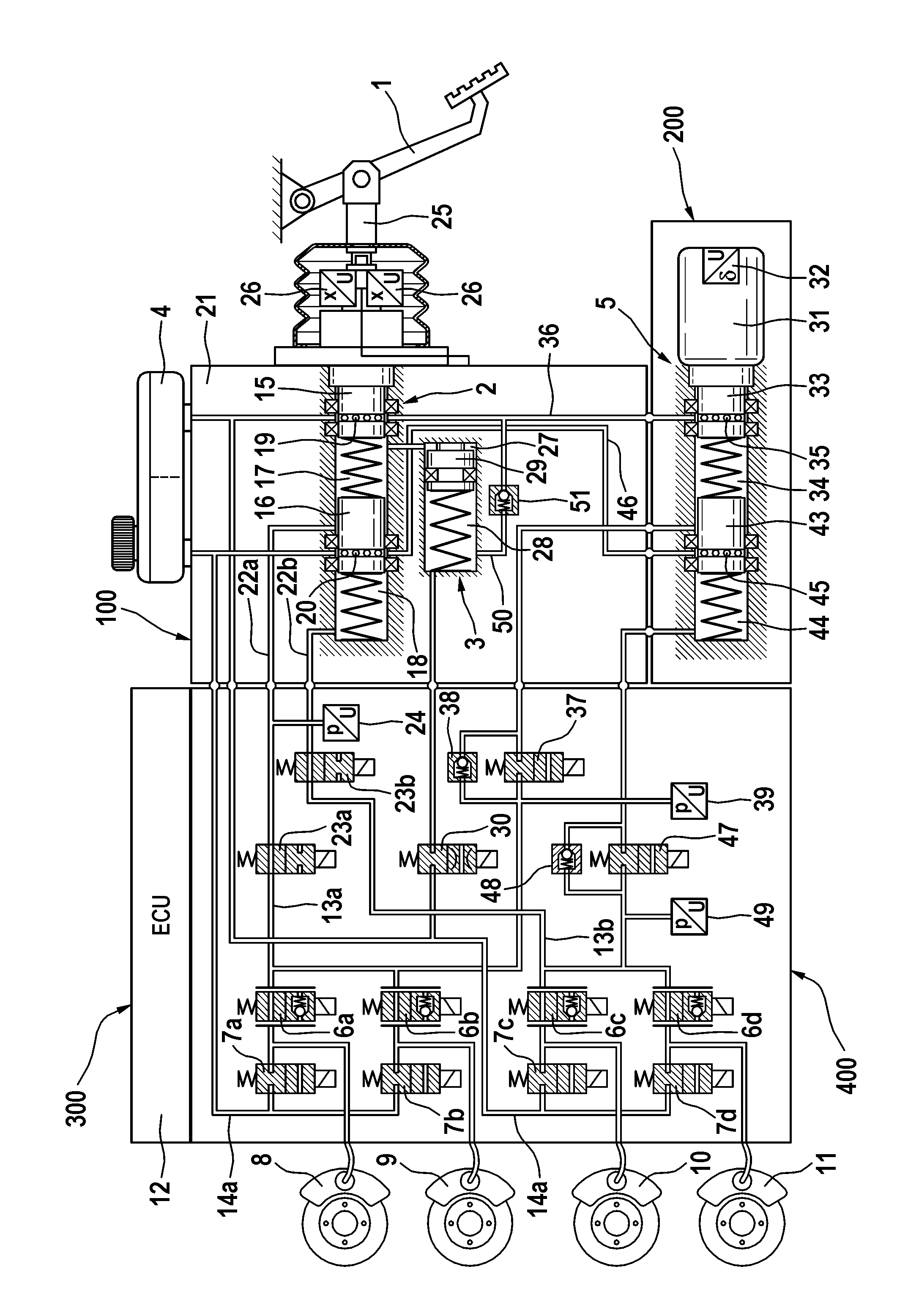
[0015]The brake system illustrated in the drawing is composed substantially of a hydraulic piston-cylinder arrangement 2 which can be actuated by means of an actuating or brake pedal 1, a travel simulation device 3 which interacts with the hydraulic piston-cylinder arrangement 2, a pressure medium reservoir 4 which is assigned to the hydraulic piston-cylinder arrangement 2, an electrically controllable pressure generating device 5, electrically controllable pressure modulation and inlet 6a-6d and outlet valves, 7a-7d, to the outlet ports of which are connected wheel brakes 8, 9, 10, 11 of a motor vehicle (not illustrated), and an electronic control and regulating unit 12 which serves for activating the electrically controllable components. The inlet ports of the inlet valves 6a-6d are supplied with a pressure, referred to as system pressure, via system pressure lines 13a and 13b, wherein pressure sensors 39 and 49 are provided for measuring the pressures prevailing in the system pre...


PUM


Abstract

A brake system for motor vehicles, which brake system can be actuated both by the vehicle driver and also independently of the vehicle driver in a “brake by wire” operating mode, is preferentially operated in the “brake by wire” operating mode, and can be operated in at least one fall-back operating mode in which only operation by the vehicle driver is possible. The brake system has inter alia an electrohydraulic pressure generating device (5) which outputs a brake system pressure, and a pressure modulation unit which has one inlet valve (6a-6d) and one outlet valve (7a-7d) per wheel brake (8, 9, 10, 11) for setting wheel-specific brake pressures derived from the brake system pressure, wherein the inlet and outlet valves (6a-6d, 7a-7d) output or transmit the brake system pressure when in the non-actuated state.

Description

CROSS-REFERENCE TO RELATED APPLICATIONS [0001]This application claims priority to German Patent Application Nos. 10 2009 029 369.8, filed Sep. 11, 2009; 10 2010 040 097.1, filed Sep. 1, 2010, and PCT / EP2010 / 063093, filed Sep. 7, 2010.FIELD OF THE INVENTION [0002]The present invention relates to a brake system for motor vehicles, which brake system can be actuated both by the vehicle driver and also independently of the vehicle driver in a “brake by wire” operating modeBACKGROUND AND SUMMARY OF THE INVENTION [0003]The system in accordance with this invention is preferentially operated in the “brake by wire” operating mode, and can be operated in at least one fall-back operating mode in which only operation by the vehicle driver is possible, having[0004]a) a brake pedal for actuating a pedal decoupling unit having a housing, having two pistons which are arranged in series and which, in the housing, delimit two pressure chambers, which pistons are subjected to an actuating force (pedal...

Claims


Application Information

Patent Timeline
IPC IPC(8): B60T13/58B60T13/68B60T7/04
CPCB60T8/4081B60T8/40
Inventor JUNGBECKER, JOHANNLINKENBACH, STEFFENDRUMM, STEFAN A.SCHIEL, LOTHARBAYER, RONALDBESIER, MARCO
Owner CONTINENTAL TEVES AG & CO OHG
Why Eureka
Try Eureka