The problem is more complicated for trucks that not only have much larger blind spots along the sides of the vehicle but also have a serious
blind spot starting in front of the right front bumper of the vehicle and extending beyond the right door.
This
blind spot is particularly serious in urban driving where small vehicles, motorcycles, pedestrians, bicycles etc. in this area can be completely hidden from the view of the driver.
This is difficult to do without knowledge of the location of the eyes of the driver.
For most systems that do not incorporate an occupant sensor capable of determining the location of the driver's eyes, there is a risk that the mirrors will be positioned wrongly thus exacerbating rather than helping the
blind spot detection problem.
Also, a
system that rotates the mirror will make the driver nervous since he or she will not be able to see the scene that he or she is accustomed to seeing in the mirror.
Any
system which displays a picture of the object on the screen that is inside the vehicle is also going to confuse the driver since he or she will not be able to relate that picture to an object such as another vehicle in the blind spot on the side of the host vehicle.
Additionally, the state of the art of such displays does not provide equally
observable displays at night or in bright
sunlight.
Thus, displays on a CRT or LCD are not natural and it is difficult for a driver to adjust to these views.
The lighting of the views is too faint when
sunlight is present and too bright when the vehicle is operating at night.
Therefore, none of these television-like displays can replace the actual visual view of the occupant.
Other systems that are based on
radar or
ultrasound have also not been widely adopted for reasons related to cost, accuracy and false alarms.
Both systems use beams of energy that can become several feet in
diameter by the time that they reach the edges of the blind spot and thus can confuse a large vehicle or a guardrail, sign, parked car etc. two lanes over with a vehicle in the blind spot.
A tradeoff exists in all such systems where, if all threatening objects are made known to the driver, the
false alarm rate becomes unacceptable and the driver soon loses confidence in the
system and ignores it.
If the
false alarm rate is kept low, many dangerous situations are ignored.
Thus, all the prior art systems discussed above have serious failure
modes.
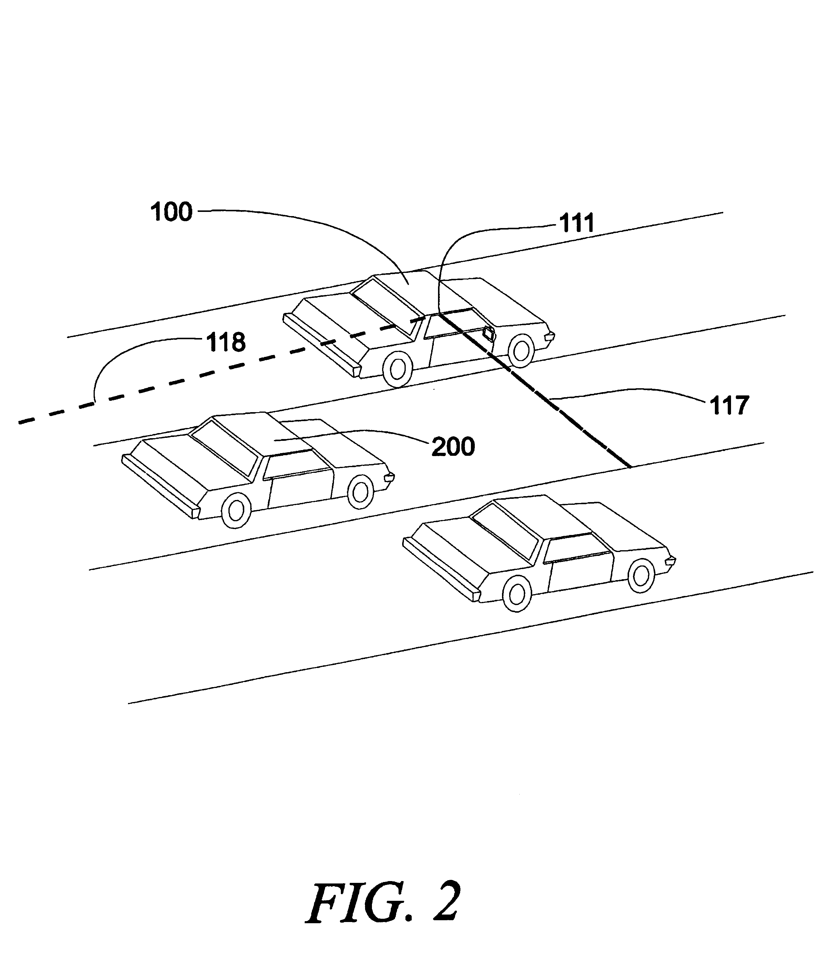
Some other problems come about when a vehicle strays into the lane of the host vehicle.
Most systems will fail to warn the operator and thus an accident can result.
Thus, the blind spot problem is really two problems relating to the motion of the potentially striking vehicle and the potentially struck vehicle.
This system must work with very high reliability and accuracy since the consequences of an error can be serious injuries or death.
Passive infrared and vision cannot provide a direct measurement of distance to an object unless part of the
field of view is illuminated by a point or
structured light.
Radar in general has a high
false alarm rate due to the large pixel size at any significant distance from the host vehicle, to multipath effects and reflections off of signs, bridges, guardrails etc.
However, for imaging applications, the
slow speed and relatively large pixel size renders ultrasonics marginal.
Also, ultrasonic
waves can be significantly distorted by thermal gradients and wind.
Their main
advantage is their low cost and small size, and main
disadvantage is their inability to determine the distance to a detected object and
slow response time.
Laser Radar: As with regular
radar, two techniques exist: (1) a pulsed-beam of infrared light coupled with time-of-flight measurements, and (2) the modulation of a
continuous light beam.
Despite its high cost, this technique offers the advantages of being insensitive to environmental conditions, but the
disadvantage of having a large pixel size.
Impulse Radar: This radar differs from FMCW in that it uses very short pulses instead of a
continuous wave.
Like FMCW radar, it is insensitive to environmental conditions, but the cost is significantly lower than FMCW.
It also has the
disadvantage of having a large pixel size resulting in a high false alarm rate and too little information to permit object identification.Capacitive and Magnetic: Capacitive and magnetic sensors are able to detect close objects (within about 2 m.
The poor resolution compared to other techniques makes it unlikely that these devices will be used for
blind spot detection since most objects are close to the vehicle.Vision Systems: These techniques are based on the use of a camera and image-
processing software.
However, these references do not disclose a camera and in fact, each
receiver is a
single pixel device.
Otherwise, they do not provide accurate
ranging.
No direct measurement of the distance is achieved, however, in some cases multiple detectors are used in such away that when the adjacent detected vehicle is very close to the
detector, that is, below the threshold distance, the sensing of the adjacent vehicle is suppressed.
The locations of the antenna, however, make it difficult to detect many objects in the side blind spots.
The particular location and velocity of such objects are also not accurately determined.
The device is based on a
single pixel having a relatively
large size making recognition and identification of the object impossible.
This is a
single pixel device and thus no imaging or object recognition is possible.
Thus, no accurate range measurement is provided.
Additionally, it provides too much information for the driver thus creating the possibility of driver
information overload.
The main problem is that the LCD driver-viewing screen is more likely to confuse than to aid the driver due to its poor dynamic
light intensity range and the ability to relate the image to the location and velocity of the object in the blind spot.
It requires multiple locations and cannot be mounted, for example, on the side rearview mirror.
As a result, many objects, such as a high speed passing vehicle, are missed.
It invariably will miss objects that move rapidly into blind spot.
It does not appear that the system can be easily adjusted for vehicles of different length.
Some problems are that this system will interfere with other vehicles having the same system.
Once again, the system will invariably miss a high-speed vehicle passing on either the right or the left since it is limited to a two
mile per hour velocity difference between the blind spot object and the host vehicle.
It also appears to be a very expensive system.
Another potential problem is that when an especially long
truck having the system of this patent is turning, the system would pick up the end of
truck and treat it as they object in the blind spot.
The problems are that no attempt is made to analyze the image or to determine its velocity and therefore, a high false alarm rate can be expected.
However, the system does not provide an image and therefore no
pattern recognition is possible.
Such a system is not sufficiently accurate to provide drivers who are attempting to merge into adjacent lines with sufficiently accurate position information to permit a safe merge under
heavy traffic without
visual contact.
The problems with this device are that this system does not know where the infrared rays are coming from.
This is an alternate method of discriminating between a vehicle and the road but one that still lacks resolution.
Unfortunately, the various figures in the patent that illustrate this phenomena are not accurate and appear to show that the positions of the vehicles relative to the subject vehicle can be visually seen which is not the case.
Also, no attempt has been made to identify and analyze objects in the blind spot and warn the driver of a pending accident.
The CCD array suffers from the problem that, due to its limited
dynamic range, it can be overwhelmed by light from the sun, for example, reflected off a vehicle or other surface.
In other words, the system knows that something is in the blind spot but does not know what it is or even accurately where it is.
There is no accurate
ranging and there will likely be a high false alarm rate with this system.
It is a one-pixel device and therefore does not permit the location of the object in the blind spot to be determined.
This device and other similar passive infrared devices will have trouble distinguishing between a small objects such as a motorcycle which is relatively close to the sensor and larger objects such as a truck which are relatively far away, for example in two lanes over.
It does not attempt to capture an image of an object in the blind spot or determine the identity of such an object and thus many non-threatening objects will appear to be threatening.
Accordingly, the system can be expected to have a high false alarm rate.
As a result, such systems miss a high speed vehicle which is in the blind spot and was not observed approaching the blind spot by the driver.
Thus, none of the prior art described above discloses a method or apparatus of monitoring the blind spot of the vehicle that analyzes an image of one or more objects that occupy the blind spot, identifying them and determining the location and
relative velocity of the objects relative to the host vehicle in a manner that permits an accurate warning to be issued to the driver of a potentially dangerous situation.
The cost of the CCD and
CMOS arrays, for example, have been expensive until recently, rendering their use for blind spot systems impractical.
Similarly, the implementation of the techniques of the above referenced patents frequently requires expensive microprocessors while the implementation with neural networks and similar trainable
pattern recognition technologies permits the use of low cost microprocessors typically costing less than $10 in large quantities.
In this case, the area covered is not as accurately controlled and a larger CCD or
CMOS array is required.
First, the
speed of sound limits the rate at which the position of the object can be updated.
Second,
ultrasound waves are diffracted by changes in air density that can occur when thermal gradients are present or when there is a high-speed flow of air past the
transducer.
Third, the resolution of
ultrasound is limited by its
wavelength and by the transducers, which are high Q tuned devices.
Finally, the fields from ultrasonic transducers are difficult to control so that reflections from unwanted objects or surfaces add
noise to the data.
The above review of a prior art blind spot detecting systems illustrates that no existing system is believed to be sufficiently adequate.
A fundamental problem is that vehicle operators are familiar with visual systems and inherently distrust all other technology.
However, there are no adequate display systems that will appear to the operator to be equivalent to an actual view of the scene.
CRTs and LCDs require driver concentration and do not have the
dynamic range of lighting that is comparable to the real world.
Either the display will be too bright at night or too dim during
daylight.
Although
radar systems can accurately measure distance to an object, they are poor at placing the object in the lateral and vertical coordinates relative to the vehicle and thus create many false alarms.
If this display is kept simple, then the problems of visual
dynamic range become much less severe.
Although a series of pulses from a
laser diode array are contemplated, other techniques will also accomplished the same goal, however, at a generally higher cost.
This technique however requires a scanning
laser system that in general, although more accurate, would be more expensive than a simple array of LEDs.
However, these techniques require considerable computational power and are not as cost-effective as the simple
LED array described above or a linear scanning LED or
laser with a
pin diode, or equivalent,
receiver as disclosed below.
If this
radiation comes from pixels other than those that are expected, then the system will know that the results are erroneous.
If that happens over a significant period of time, then the operator of the vehicle is warned that the
blind spot detection system is non-operational.
Using sophisticated
image processing and mathematical techniques, however, it is expected that those periods of non-functionality will be minimal.
The vehicle operator however will not be subjected to a false alarm but instead will be told that the system is temporarily non-operational due to excessive
sunlight etc.
Unfortunately, the blind spot problem is significantly more complicated.
The road may be curved and the lane changing maneuver might be quite easily accomplished, however, based on the geometry of the blind spot detecting system, using prior art systems, the driver is warmed that he cannot execute such a lane change.
This may be fallacious in that the vehicle that the system determines is in the blind spot may actually be in a different lane.
Under the stress of congested driving conditions, the driver will not tolerate an erroneous message and thereby he might lose confidence in the system.
This is very disquieting to a vehicle operator who was told that something is there but not what that something is.
This is a real world situation, yet all existing
blind spot detection systems would give an erroneous answer, or no answer at all, to the vehicle operator.
The particular geometry of the road is unknown to vehicles today, therefore, a blind spot detection system cannot use information that says, for example, that the road is about to take a sudden curve to the left, in its decision-making function.
Unfortunately, under normal driving conditions only about 70% of drivers use their turn signals as an indication of a lane change.
The driver must be warned when he is about to change lines but the activation of a turn
signal is not sufficient.
However, these computationally intensive systems are probably not applicable at this time.
Whereas a
rumble strip type message can be sent to the driver, control of the vehicle cannot be assumed by the system since the road in fact may be executing a sharp curve and taking control of the vehicle might actually cause an accident.
Since the system will not know whether the driver is following a curve in the road or in fact changing lanes, the driver will be able to easily overcome this
added resistance but nevertheless, it should indicate to the driver that there is a potential problem.
As discussed above, many technologies are available for measuring distance, some more expensive than others.
In other words, the dynamic range of light that can be emitted by conventional displays is insufficient to display other than the most simple messages.
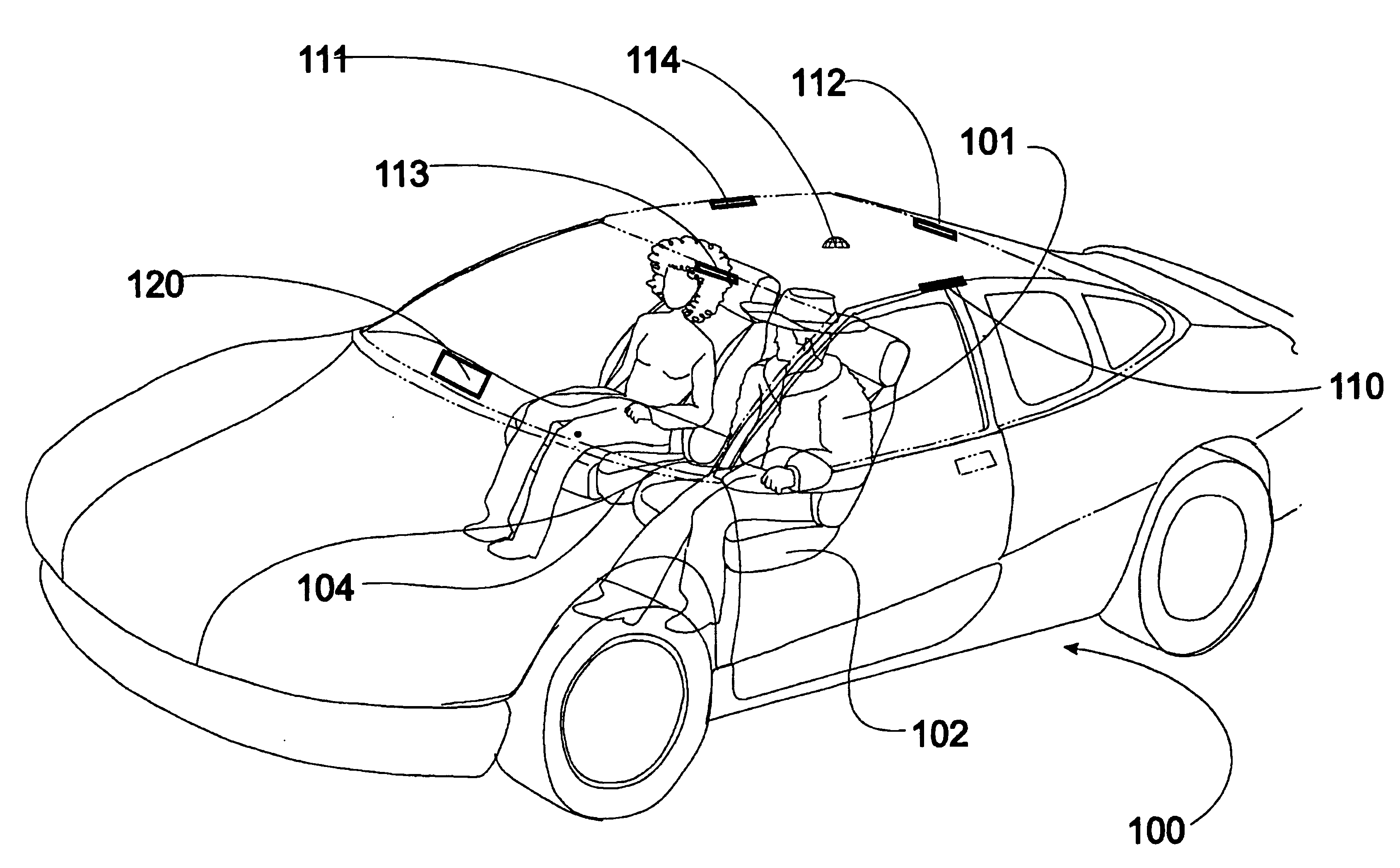
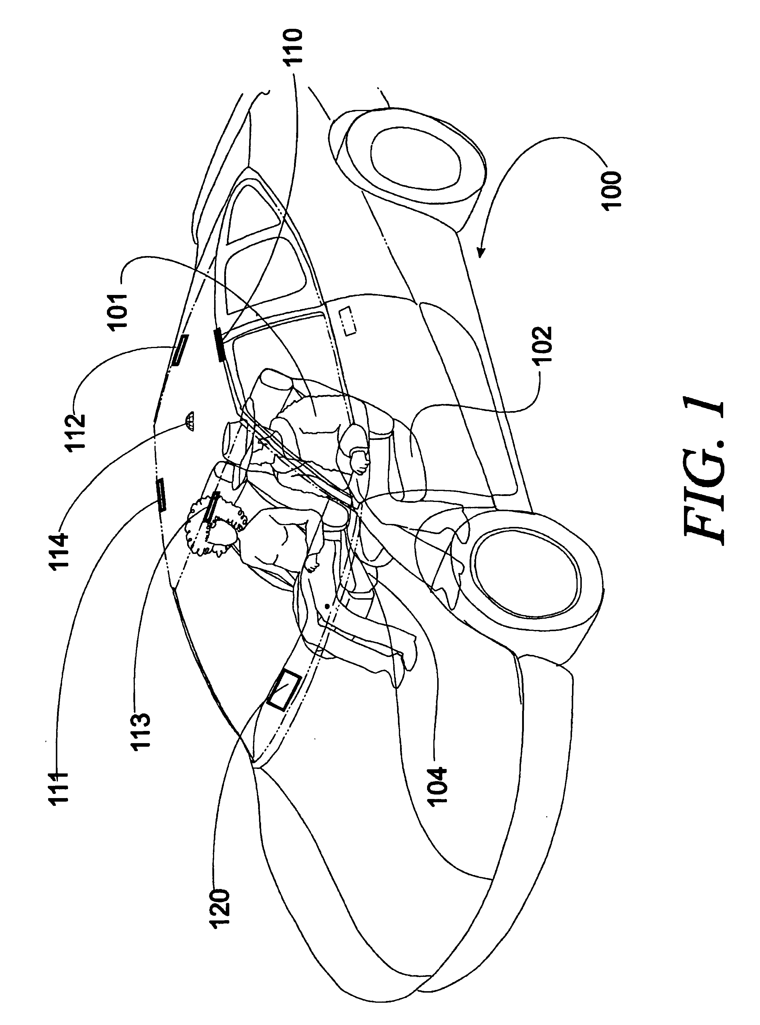
It is been observed that drivers adjust side rear view mirrors over an extended range that renders the use of the mirror angle unsuitable for determining the position of the driver's eyes.
There will be conditions when the optical system from the
CMOS camera has deteriorated due to
contamination on the lens.
The blind spot problem for trucks is particularly difficult.
However, the truck driver is also unable to see objects that are in another blind spot extending from forward of the front of the vehicle back typically 25 feet.
Trucks also have blind spots behind the trailer which are problematic during
backup maneuvers.

