
System and method for improving vehicle operator driving assistance of automotive vehicle

a technology for vehicle operators and drivers, applied in anti-collision systems, special data processing applications, pedestrian/occupant safety arrangements, etc., can solve the problem that the time at which the vehicle makes a traffic lane change on which the vehicle is traveling cannot be produced to the driver

Inactive Publication Date: 2006-08-01
NISSAN MOTOR CO LTD
View PDF12 Cites 185 Cited by
  • Summary
  • Abstract
  • Description
  • Claims
  • Application Information

AI Technical Summary

Benefits of technology

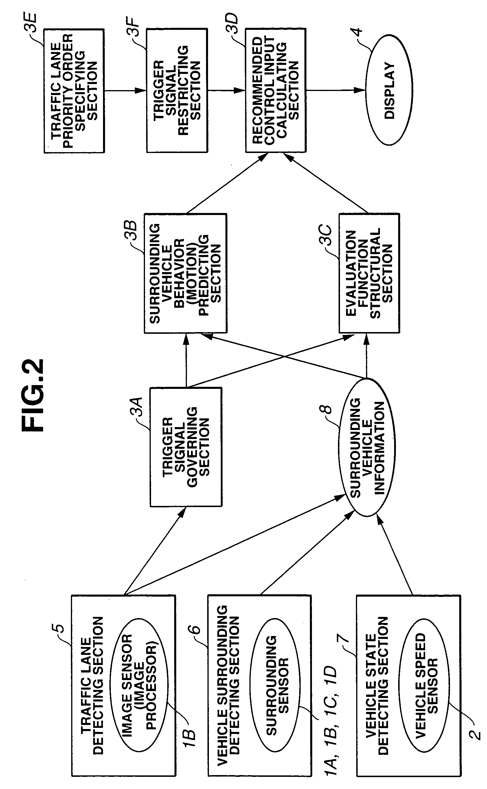
The present invention provides a system and method for improving the driving assistance of an automotive vehicle by predicting the future movements of surrounding vehicles and recommending to the driver when and how to make a traffic lane change. This helps the driver to make informed decisions and reduces the risk of accidents. The system includes a sensor to detect the vehicle's surroundings, a host vehicle condition sensor, a lane sensor, and a motion predictor. The system calculates a rating for the driver's driving operation and recommends acceleration timing and a lane change trigger signal based on the predicted movements of the surrounding vehicles. The recommended operation indicator also prevents new lane change trigger signals until a forward lane change operation is completed. The technical effect of this invention is to improve driving safety and assist drivers in making informed decisions when making traffic lane changes.

Problems solved by technology

However, the previously proposed driver's driving assistance improving system simply traces the value of the risk potential, a systematic prediction is not considered to be inserted into the driving operation, and, thus, a timing at which the vehicle makes a traffic lane change on which the vehicle is traveling cannot be produced to the driver.

Method used


Image

  • System and method for improving vehicle operator driving assistance of automotive vehicle
  • System and method for improving vehicle operator driving assistance of automotive vehicle
  • System and method for improving vehicle operator driving assistance of automotive vehicle

Examples


first embodiment

[0026](First Embodiment)

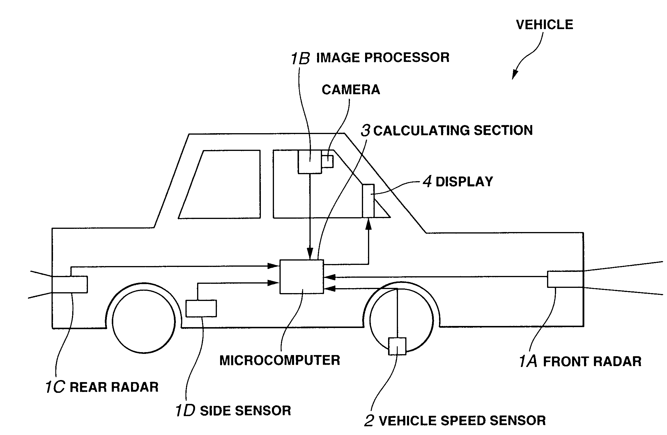
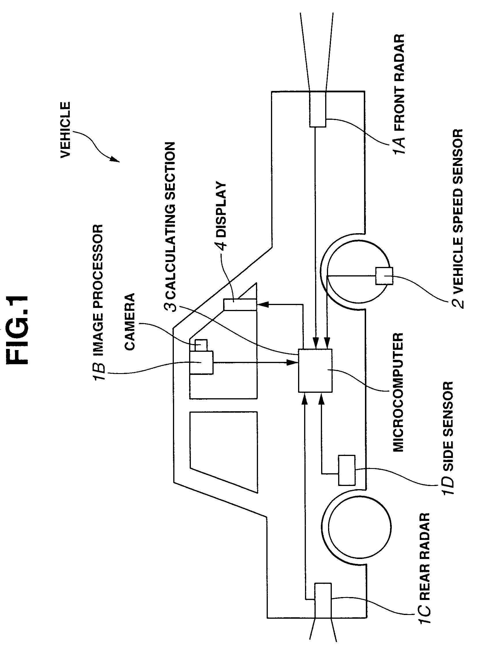
[0027]FIGS. 1 through 6 show a first preferred embodiment of a system for improving a vehicle operator driving assistance of an automotive vehicle in a first preferred embodiment according to the present invention. FIG. 1 shows a system configuration view of the vehicle operating driving assistance improving system in the first preferred embodiment needed to construct the system for improving the vehicle operator driving assistance according to the present invention.

[0028]In FIG. 1, a front radar 1A is mounted on a front surface of an automotive vehicle (or simply called a vehicle) to measure positions of a plurality of surrounding vehicles placed ahead of the vehicle. An image sensor (or image processor) 1B is mounted on an appropriate position of a vehicular front surface to compensate for a measurement information of front radar 1A and to detect traffic lanes drawn on a traveling road. Rear radar 1C is mounted on a rear surface of the vehicle to measure th...

second embodiment

[0092](Second Embodiment)

[0093]FIGS. 7 through 10F show a second preferred embodiment of the vehicle operator driving assistance improving system. FIG. 7 shows an arrangement of the driving assistance improving system in the second embodiment according to the present invention. A basic structure in the second embodiment is the same as described in the first embodiment shown in FIG. 1. In the second embodiment, a GPS (Global Positioning System) signal receiver 9 and a map data base 10 are added. Along with this addition, the functional block diagram is different as shown in FIG. 8. A basic processing flow in calculating section 3 is the same as shown in FIG. 6 described in the first preferred embodiment. In this embodiment, the operation of the system in a scene in which the number of the traffic lane is increased. FIG. 9 shows a situation in which vehicle 0 is traveling on the left lane of the one-side three-traffic-lanes road, one traffic lane is increased at a leftmost side of the...

third embodiment

[0109](Third Embodiment)

[0110]FIGS. 11 and 12A through 12C show a scene and operation in a third preferred embodiment of the driving assistance improving system. A basic structure in the driving assistance improving system of the third embodiment is the same as described in the second embodiment. FIG. 7 described in the second embodiment is applicable to the third embodiment and FIG. 8 described in the second embodiment is also applicable to the third embodiment. The processing flow is also the same as that shown in the flowchart of FIG. 6 described in the first embodiment.

[0111]FIG. 11 shows the scene in which vehicle 0 is traveling on the center lane of the road of the one-side, three-traffic lanes and the scene in which vehicle 1 is traveling on the front portion of the same center lane, vehicle 2 is traveling in the backward position of (behind) vehicle 0, and vehicle 3 is traveling in the front position of the right traffic lane with respect to vehicle 0. The traveling vehicle ...


PUM


Abstract

In system and method for improving operator driving assistance of an automotive vehicle, at an indication of acceleration timing and magnitude and the lane change timing, a lane change necessity is calculated and a lane change trigger signal is produced while the host vehicle is operated on a road that has at least three lanes and, at the calculation of the lane change necessity and at the production of the lane change signal, a new lane change trigger signal is prohibited to indicate until a forward lane change operation is deemed to be completed, in a case where the vehicle is traveling on a multiple number traffic lane road.

Description

BACKGROUND OF THE INVENTION[0001]1. Field of the Invention[0002]The present invention relates to system and method for improving vehicle operator (driver's) driving assistance of an automotive vehicle.[0003]2. Description of the Related Art[0004]There are many patent applications regarding previously proposed vehicle operator driving assistance systems to assist the vehicle driver's driving. A Japanese Patent Application First Publication No. Heisei 10-211886 published on Aug. 11, 1998 exemplifies a previously proposed vehicle operator driving assistance improving system. In the previously proposed vehicle operator driving assistance improving system disclosed in the above-described Japanese Patent Application First Publication, a potential risk magnitude (so-called, a risk potential) is defined on the basis of a relative movement state with each of surrounding vehicles (obstacles inclusive) and a value of an assistance torque to a vehicular steering system or steering reaction forc...

Claims


Application Information

Patent Timeline
Patent Type & Authority Patents(United States)
IPC IPC(8): G06F7/00B62D6/00B60R21/00B62D101/00G01S13/86G01S13/93G05D1/02G08G1/16
CPCB60W40/02B60W50/08G01S13/867B60W50/14G01S13/86G01S2013/9353G01S2013/932
Inventor NISHIRA, HIKARUKAWABE, TAKETOSHI
Owner NISSAN MOTOR CO LTD
Learn More