Control apparatus of vehicle

a technology of control apparatus and vehicle, which is applied in the direction of distance measurement, instruments, applications, etc., can solve the problem of not being able to simply stop the vehicl

Inactive Publication Date: 2015-06-04
HONDA MOTOR CO LTD
View PDF19 Cites 176 Cited by
  • Summary
  • Abstract
  • Description
  • Claims
  • Application Information

AI Technical Summary

Benefits of technology

[0025]With this configuration, the final stop position is determined based on location information of medical institutions. Accordingly, it is possible to stop the unable-to-drive vehicle near a medical institution and to promptly perform the life-saving activity for the driver of the unable-to-drive vehicle.

Problems solved by technology

However, for promptly perform the life saving activity for the driver, it is not sufficient to simply stop the vehicle.

Method used


Image

  • Control apparatus of vehicle
  • Control apparatus of vehicle
  • Control apparatus of vehicle

Examples


first embodiment

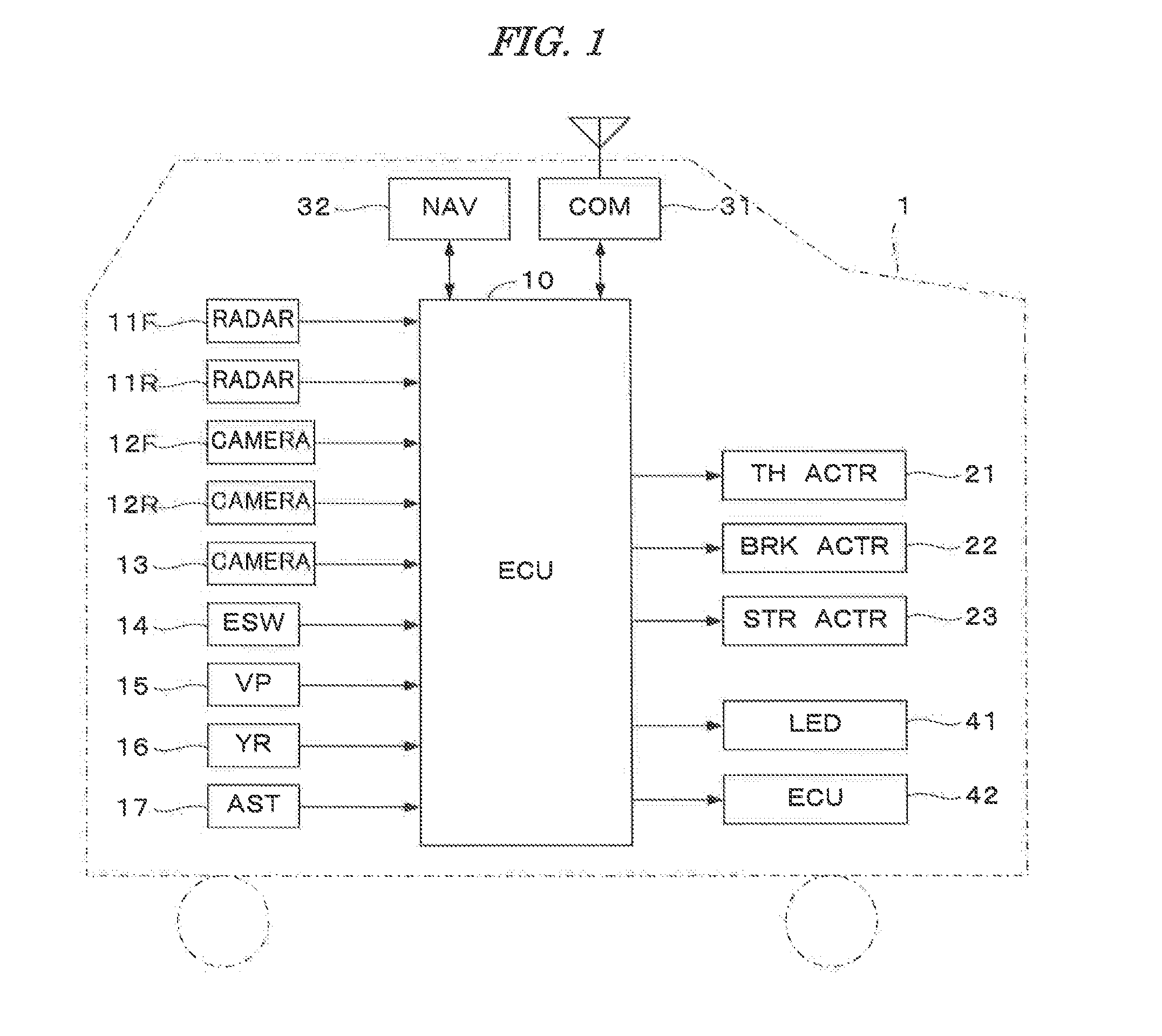
[0034]FIG. 1 is a block diagram showing a configuration of a control apparatus of a vehicle according to one embodiment of a present invention. This control apparatus is mounted on a vehicle 1, and the control apparatus is provided with an electronic control unit (hereinafter referred to as “ECU”) 10, radars 11F and 11R connected to the ECU 10, cameras 12F, 12R, and 13, an emergency switch 14, a vehicle speed sensor 15, a yaw-rate sensor 16, a steering angle sensor 17, a communication unit 31, a navigation unit 32, a throttle actuator 21, a brake actuator 22, and a steering actuator 23. The cameras 12F and 12R respectively obtains images of a forward view and a backward view of the vehicle 1. The camera 13 obtains an image of a head of the driver of the vehicle 1. The emergency switch 14 is provided for the driver to turn on upon an emergency, such that the driver is going to be unconscious by a heart attack or the like. The vehicle speed sensor 15 detects a vehicle speed (running s...

second embodiment

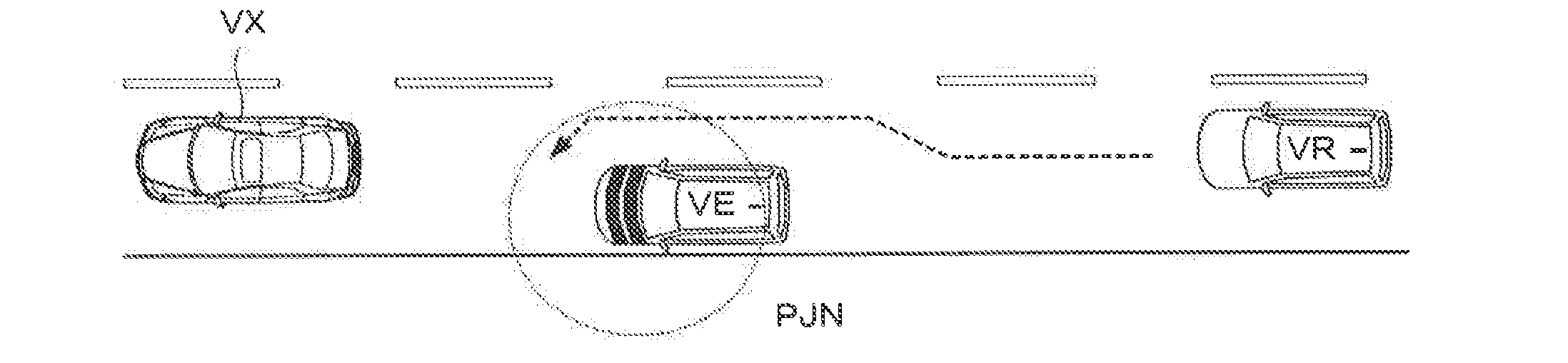
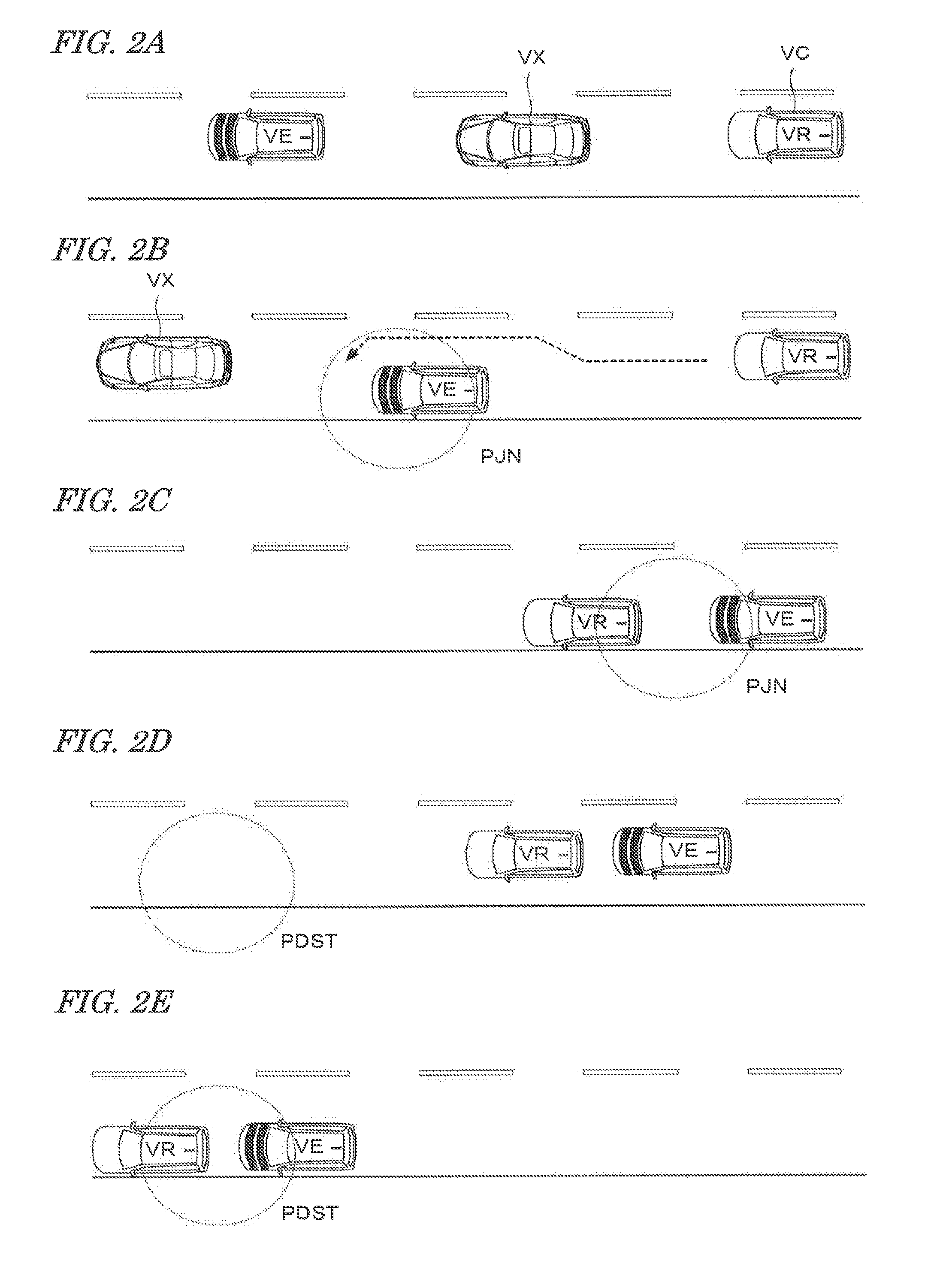
[0075]In this embodiment, if the driver has become the unable-to-drive state, the unable-to-drive vehicle VE is promptly stopped, the stop position PSTP is determined as the joining point PJN, and the leading vehicle VR runs toward the joining point PJN. Further, in the above-described first embodiment, only when the vehicle VC having the same control apparatus as that of the vehicle VE runs on the same road on which the vehicle VE runs, the vehicle VC is adapted to the leading vehicle VR. In this embodiment, guidance by the navigation unit is performed until the vehicle VC reaches a stop road RSTP on which the unable-to-drive vehicle VE stops, the driver of the vehicle VC is advised by the navigation unit that the vehicle VC should become the leading vehicle VR, and after the time the vehicle VC reaches the stop road RSTP, the autonomous and automatic driving of the vehicle VC as the leading vehicle VR is performed to the joining point PJN. This embodiment is the same as the first ...


PUM


Abstract

A control apparatus of a vehicle is provided. In the control apparatus, an unable-to-drive state of the driver of the vehicle is detected or determined. The unable-to-drive state is a state where the driver is unable to drive the vehicle. When the emergency that the driver has become the unable-to-drive state is detected or determined, the detection or determination result is notified to the outside. A leading vehicle which is adapted to leading the vehicle based on the notification, is recognized. Automatic follow-up running control is performed wherein the vehicle is made to automatically follow the leading vehicle.

Description

BACKGROUND OF THE INVENTION[0001]1. Field of the Invention[0002]The present invention relates to a control apparatus of a vehicle, for stopping an unable-to-drive vehicle at an appropriate position, the unable-to-drive vehicle being a vehicle of which the driver has become an unable-to-drive state where the driver is unable to drive the vehicle, due to, for example, a heart attack or a cerebral infarction.[0003]2. Description of the Related Art[0004]Japanese patent laid-open publication No. 2010-125923 discloses a vehicle control apparatus for stopping a vehicle at an appropriate position when the driver has become the unable-to-drive state. According to this apparatus, the stop position of the vehicle is decided according to the road configuration when the driver has become unable to drive the vehicle, automatic driving of the vehicle is performed to the decided position, and the vehicle is stopped at the position. For example, when the vehicle runs on a left-curved one-lane road w...

Claims


Application Information

Patent Timeline
Patent Type & Authority Applications(United States)
IPC IPC(8): G05D1/00A61B5/18G05D1/02
CPCG05D1/0088A61B5/18G05D1/0287B60K28/06B60W30/165G05D1/0295G05D2201/0213G05D1/0061B60W2540/26B60W50/12B60W2540/18B60W50/082B60W2520/14B60W2520/10B60W2556/50B60W2040/0827G08G1/22G08G1/20B60W2040/0836B60W2040/0845B60W2540/225B60W2540/221B60W2556/65B60W2756/10B60W2420/52B60W2420/403
Inventor OHMURA, SHIGERUOSHIDA, KEI
Owner HONDA MOTOR CO LTD
Why Eureka
Try Eureka