Lighting device, display device, and television receiver
a technology of display device and light source, which is applied in the field of light source device, display device, and television receiver, can solve problems such as difficulty in achieving complete uniformity, and achieve the effect of suppressing uneven brightness
- Summary
- Abstract
- Description
- Claims
- Application Information
AI Technical Summary
Benefits of technology
Problems solved by technology
Method used
Image

Examples
first embodiment
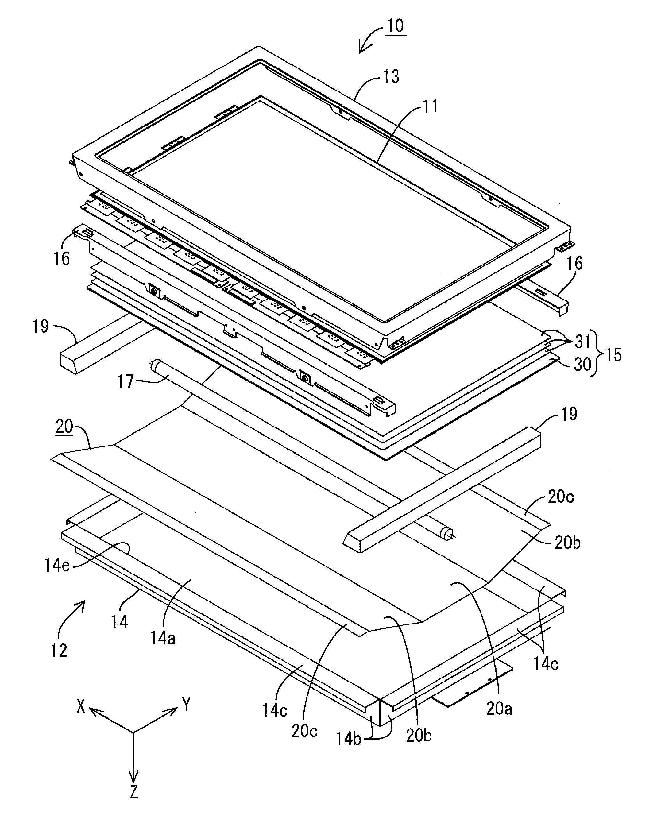
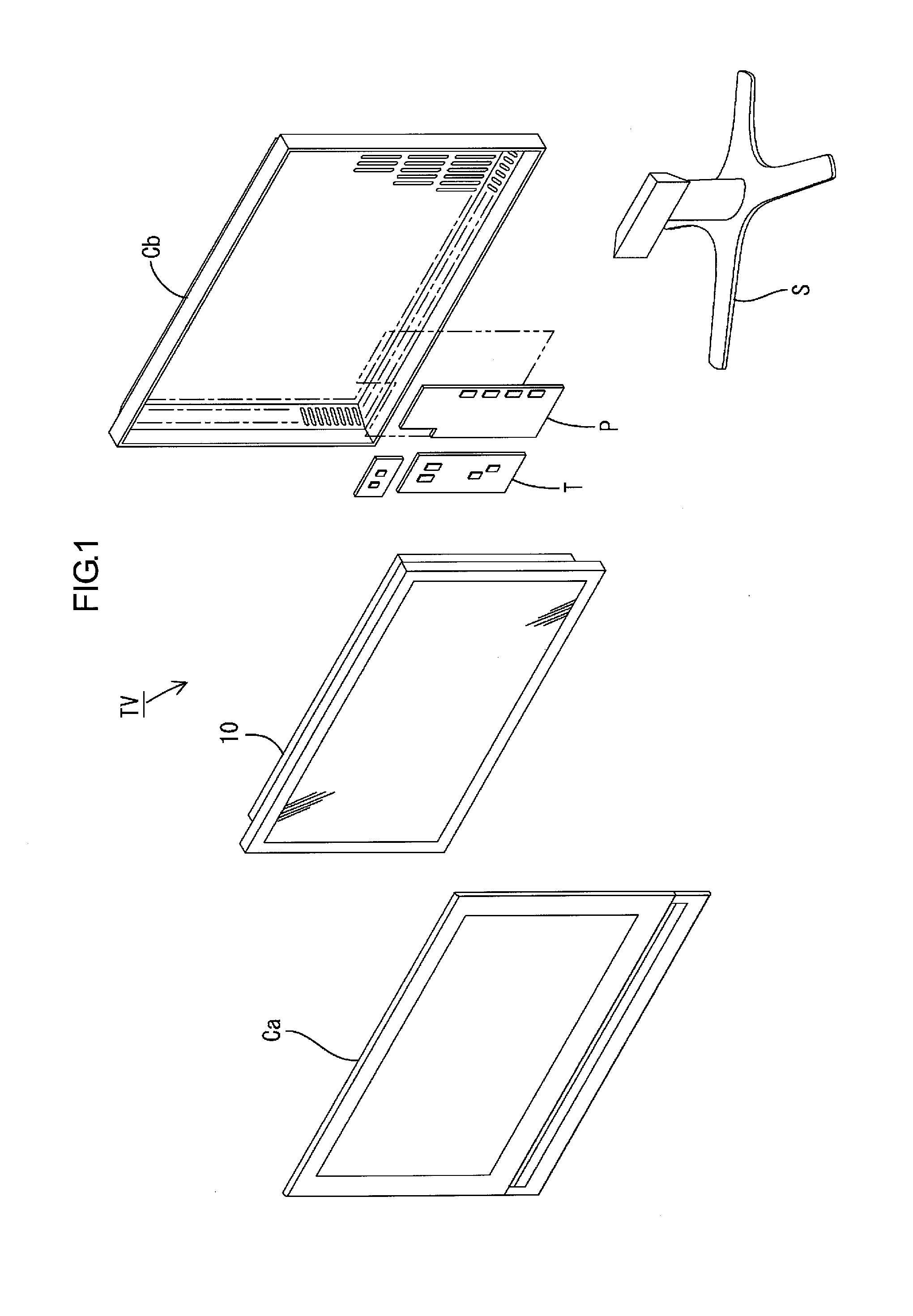
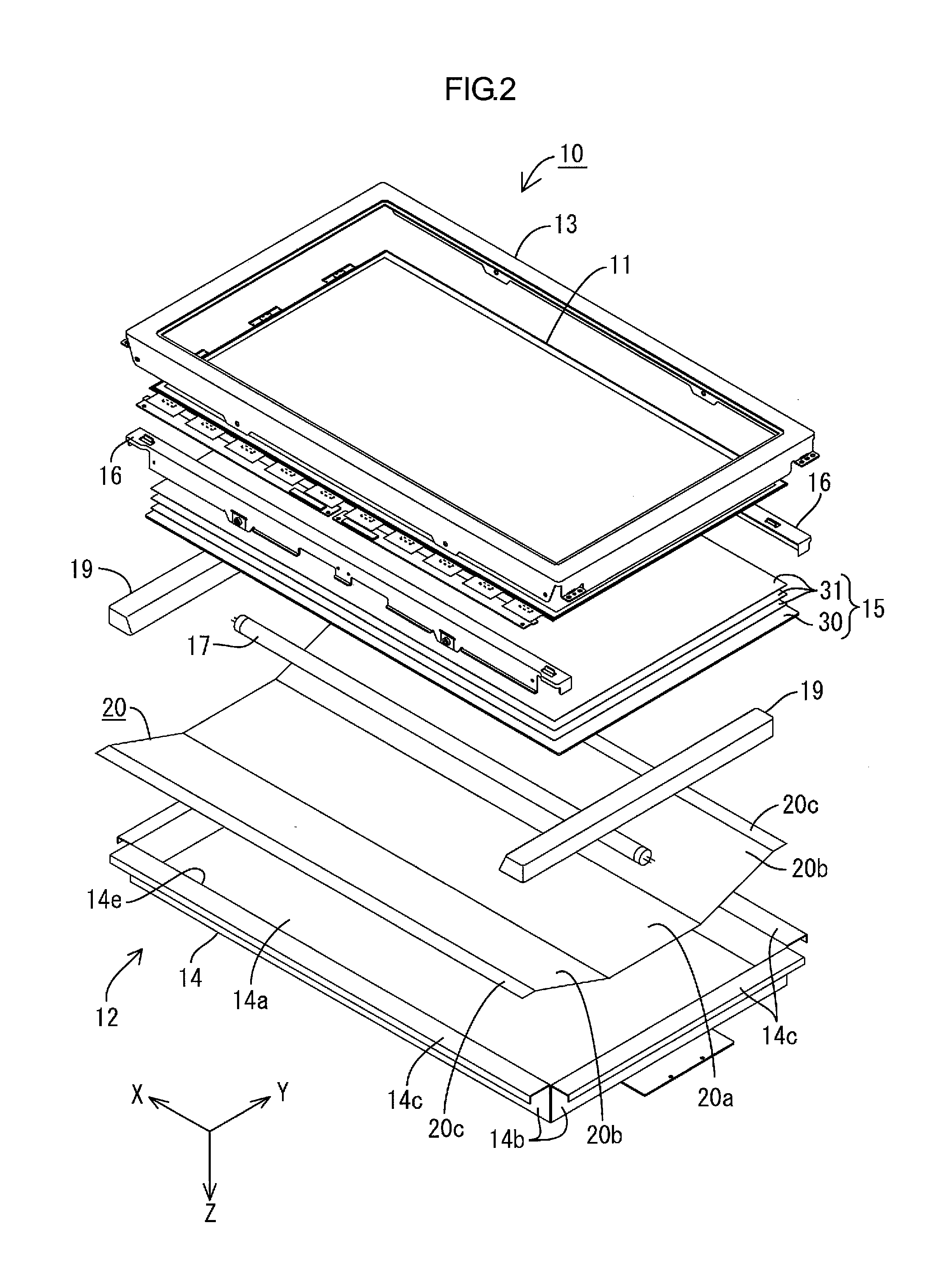
[0041]A first embodiment of the present invention will be described with reference to FIGS. 1 to 10. First, a configuration of a television receiver TV including a liquid crystal display device 10 will be described.
[0042]FIG. 1 is an exploded perspective view showing a schematic configuration of the television receiver of this embodiment. FIG. 2 is an exploded perspective view showing a schematic configuration of the liquid crystal display device included in the television receiver shown in FIG. 1. FIG. 3 is a sectional view showing a sectional configuration taken along the short-side direction of the liquid crystal display device shown in FIG. 2. FIG. 4 is a sectional view showing a sectional configuration taken along the long-side direction of the liquid crystal display device shown in FIG. 2. FIG. 5 is a plan view showing an arrangement configuration of a hot cathode tube and a reflection sheet in a chassis included in the liquid crystal display device shown in FIG. 2. Note that ...
examples
[0077]Given below are an example using the reflection sheet 20 according to the embodiments described above and comparative examples using reflection sheets having configurations different from that of the embodiments described above. Results of experiments on the degree of visibility of uneven brightness are shown in Table 1 below and FIG. 10. In the comparative experiments, four types of reflection sheets having different ratios between the short-side dimension of the bottom portion and that of the rising portion were prepared, and each reflection sheet was housed in the chassis. Further, the hot cathode tube turned on in the state where the diffuser plate is arranged at the opening of the chassis was visually observed from the front. In Table 1, “⊚” represents the case where the uneven brightness is not viewed; “◯” represents the case where almost no uneven brightness is viewed; “Δ” represents the case where the uneven brightness is slightly viewed; and “X” represents the case wh...
first modified example
of the First Embodiment
[0101]A first modified example of the first embodiment will be described with reference to FIG. 11. Here, a configuration in which the shape of rising portions 20b-1 is changed is illustrated. FIG. 11 is a sectional view taken along the short-side direction in a liquid crystal display device using a reflection sheet according to this modified example.
[0102]As shown in FIG. 11, the rising portions 20b-1 have a sectional shape of a substantially arcuate shape (bow-like shape) taken along the Y-axis direction. Specifically, the rising portions 20b-1 have a substantially arcuate shape curved to the back side, and the entirety thereof is arranged to recede to the side of the bottom plate 14a from a line (chord) connecting the rising proximal portion and the rising distal portion. A rising angle of each rising portion 20b-1 from the bottom portion 20a is substantially the same as that of the first embodiment described above. This rising angle is an angle formed by t...
PUM
 Abstract
Description
Claims
Application Information