Eureka AIR delivers breakthrough ideas for toughest innovation challenges, trusted by R&D personnel around the world.

Border structure for viewable area of electronic paper display

Active Publication Date: 2012-07-05
E INK HLDG INC
View PDF3 Cites 1 Cited by
  • Summary
  • Abstract
  • Description
  • Claims
  • Application Information

AI Technical Summary

Benefits of technology

[0009]One objective of the present invention is to disclose a border structure for viewable area of electronic paper display, which can enhance the adhesive strength of the glue layer.
[0014]The glue layer is disposed on the border electrode and has on its bottom surface at least one downward extruding portion for enhancing the adhesive strength of the glue layer.
[0016]To make it easier for our examiner to understand the objective of the invention, its structure, innovative features, and performance, we use preferred embodiments together with the accompanying drawings for the detailed description of the invention.

Problems solved by technology

However, when peel-offs occur in the interface between the glue layer 111 and the border electrode 120 under an environment of high temperature and high humidity, the electrical field distribution over the electrophoretic display layer 112 will become non-uniform, causing mura defects (uneven defects or inconsistent defects) to occur in the display of the edge band pattern.

Method used


Image

  • Border structure for viewable area of electronic paper display
  • Border structure for viewable area of electronic paper display
  • Border structure for viewable area of electronic paper display

Examples


Embodiment Construction

[0024]The present invention will be described in more detail hereinafter with reference to the accompanying drawings that show the preferred embodiment of the invention.

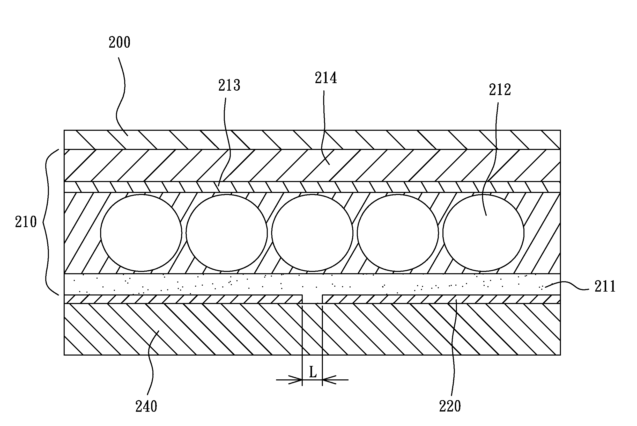
[0025]To enhance the adhesive effect of the glue layer so as to reduce the chance of mura defects occurring in the border regions of viewable area, the present invention proposes a border structure for viewable area of electronic paper display, in which a glue layer has on its bottom surface a plurality of downward extruding portions. Please refer to FIG. 3, which illustrates a partial sectional view of a border structure for viewable area of electronic paper display according to a preferred embodiment of the present invention. As can be seen in the figure, the border structure for viewable area includes, from top to bottom, a protection sheet 200, a FPL 210, a border electrode 220, and a planarization layer 240, wherein the FPL 210 includes, from bottom to top, a glue layer 211, an electrophoretic display layer 212,...


PUM


Abstract

A border structure for viewable area of electronic paper display, including: a planarization layer; a border electrode, made of metal and disposed on the planarization layer; a glue layer, disposed on the border electrode and having on its bottom surface at least one downward extruding portion for enhancing its adhesive strength; and an electrophoretic display layer, disposed on the top surface of the glue layer.

Description

BACKGROUND OF THE INVENTION[0001]1. Field of the Invention[0002]The present invention relates to an electronic paper display, especially to a border structure for viewable area of an electronic paper display, capable of reducing the chance of mura defects (uneven defects or inconsistent defects) occurring in the electronic paper display.[0003]2. Description of the Related Art[0004]As the pixels around the border of the viewable area of an electronic paper display are prone to be covered by an edge frame, four long rectangular edge regions of the viewable area are usually preserved as border regions with four corresponding long rectangular border electrodes equipped underneath. When in operation, the electronic paper display will apply a voltage to the border electrodes to determine the display color in the border regions. The display color in the border regions is usually set to be close to the color—black for example—of the edge frame of the electronic paper display, so that the bo...

Claims


Application Information

Patent Timeline
IPC IPC(8): G02F1/167G02F1/1676
CPCG02F1/167G02F2001/1676G02F2001/133388G02F1/1676G02F1/133388
Inventor LIN, CHUN-YILIU, CHUAN-FENGCHEN, JIA-HUNG
Owner E INK HLDG INC
Why Eureka
Eureka Blog
Learn More