Eureka AIR delivers breakthrough ideas for toughest innovation challenges, trusted by R&D personnel around the world.

Method for Producing Hose with Sealing Layer

Active Publication Date: 2008-10-09
TOKAI RUBBER IND LTD
View PDF2 Cites 12 Cited by
  • Summary
  • Abstract
  • Description
  • Claims
  • Application Information

AI Technical Summary

Benefits of technology

[0057]When the plasma treatment is applied to the hose (hose body) with the large inner diameter at the same flow rate of the plasma gas for the same time period as to a hose (hose body) with a small inner diameter, as a part of the plasma gas fed to the interior of the hose body just passes through the center portion of the hollow interior of the hose body without acting on the inner surface of the hose body in the hose with the large inner diameter, the plasma gas fed to the interior of the hose body does not entirely act on the inner surface of the hose body with high efficiency. It is assumed that thereby the effect of modifying the inner surface of the hose body with the large inner diameter is lowered.
[0072]The atmospheric pressure plasma does not require batch processing to achieve vacuum environment for a vacuum plasma, and may be produced continuously or constantly. In the vacuum plasma, there is a fear that plasticizer such as oil may be precipitated from the hose body during the treatment according to the conditions such as vacuum level of batch processing or time period for batch processing to achieve the vacuum environment, and when vacuum is shut off after the treatment, exuded oil etc. may attach or re-attach on a surface of the hose body. On the contrary, the atmospheric pressure plasma does not require the batch processing to achieve vacuum, and does not cause a problem of attachment or re-attachment of oil etc. on the surface of the hose body.

Problems solved by technology

However, when the hose 200 and the metal pipe 204 are connected by use of such resin connector 202, there is fear that the connector 202 hits against other parts or components and is broken in a car collision.
So, when the hose is connected to the metal pipe by force-fitting the metal pipe directly and relatively into the hose, it is difficult to secure sealing properties in a connecting portion of the hose.
However, in the seal provided by the O-ring, there is a problem that the O-ring may be displaced during force-fitting of the hose, or the O-ring may move rotationally in the connecting portion when a rocking force acts on the metal pipe, and the hose, etc.
However, a longest metal pipe for piping of a motor vehicle is as long as about 5 m. In fact, it is difficult to form the sealing layer made of the elastic material on an outer surface of such a long metal pipe.
However, such material of high chemical resistance is chemically inactive and is less adhesive.
However, actually, the result of the corona treatment was found not satisfactory.
Thus, in the corona treatment, it is difficult to control a voltage between a pair of the electrodes (208, 216).
As a result, there is a problem that an adhesion strength of the sealing layer 218 is very low on the flared portion 214.
However, the following problem is found in the subsequent study.
However, a desired level of an inner surface modification was not achieved sufficiently, namely, a sealing layer cannot be adhered with desired adhesion strength.
And, the method of increasing the flow-rate of the plasma gas or the duration time period of the plasma treatment is not always advantageous in view of large-scale production of the hose 210 even if the desired surface modification is achieved.

Method used


Image

  • Method for Producing Hose with Sealing Layer
  • Method for Producing Hose with Sealing Layer
  • Method for Producing Hose with Sealing Layer

Examples


Embodiment Construction

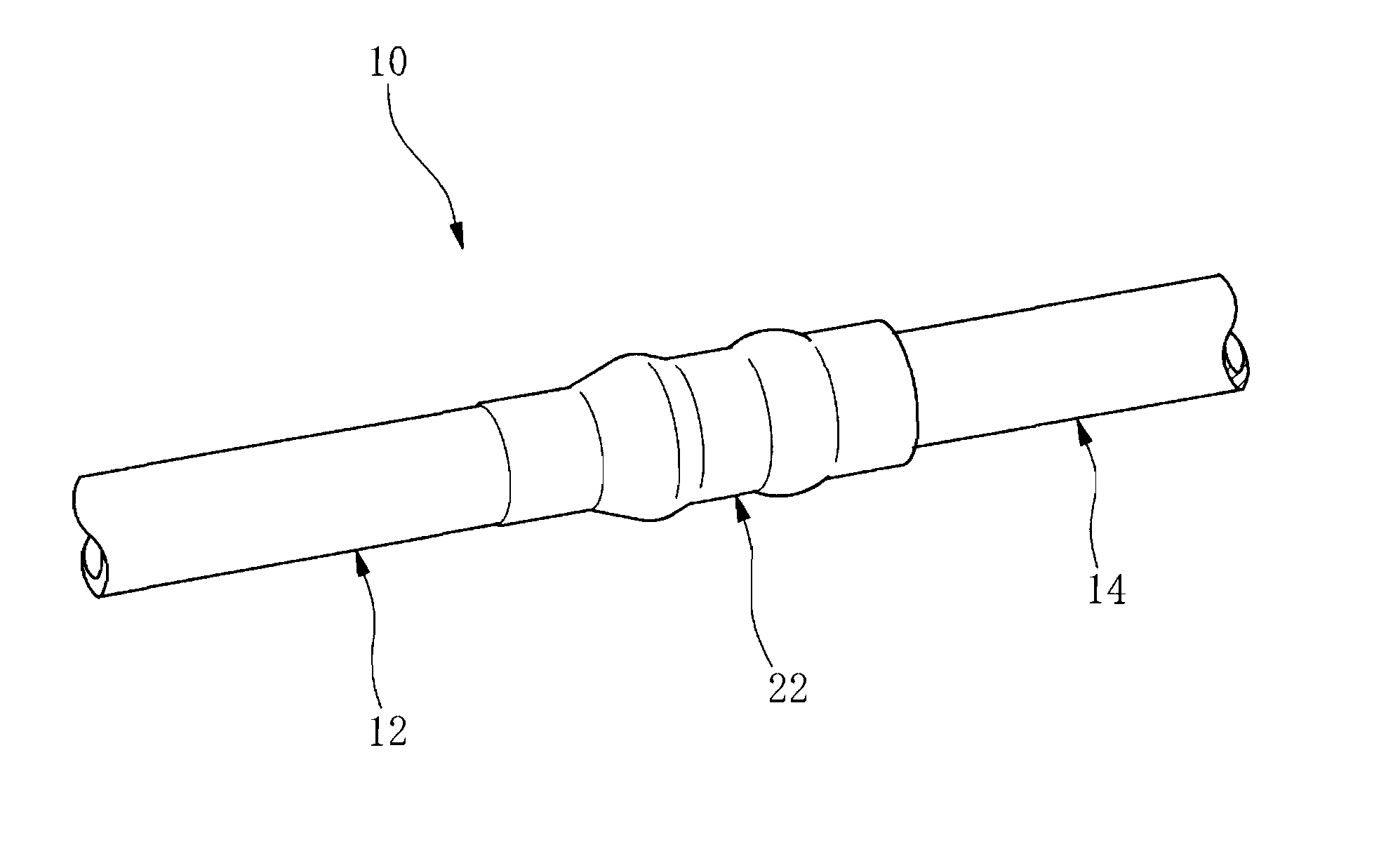
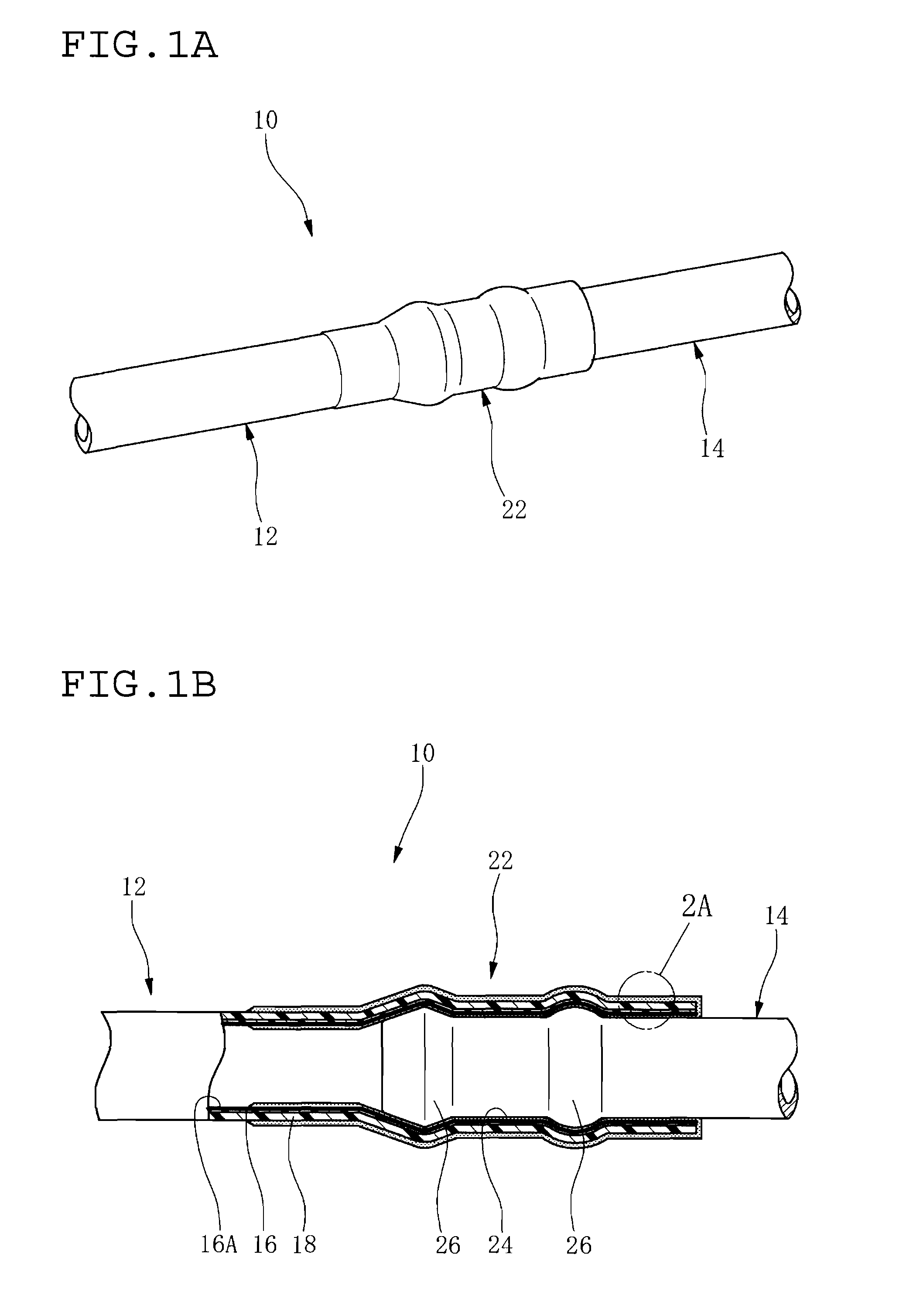
[0096]In FIG. 1A, reference numeral 10 indicates so-called direct-connect hose assembly by assembling a hose 12 and a metal pipe 14 in unitary and directly fitting relation to each other. The hose 12 is used, for example, as an automotive fuel conveying hose. FIG. 1 B shows a structure of a connecting region between the hose 12 and the metal pipe 14, with a sectional view of the hose 12.

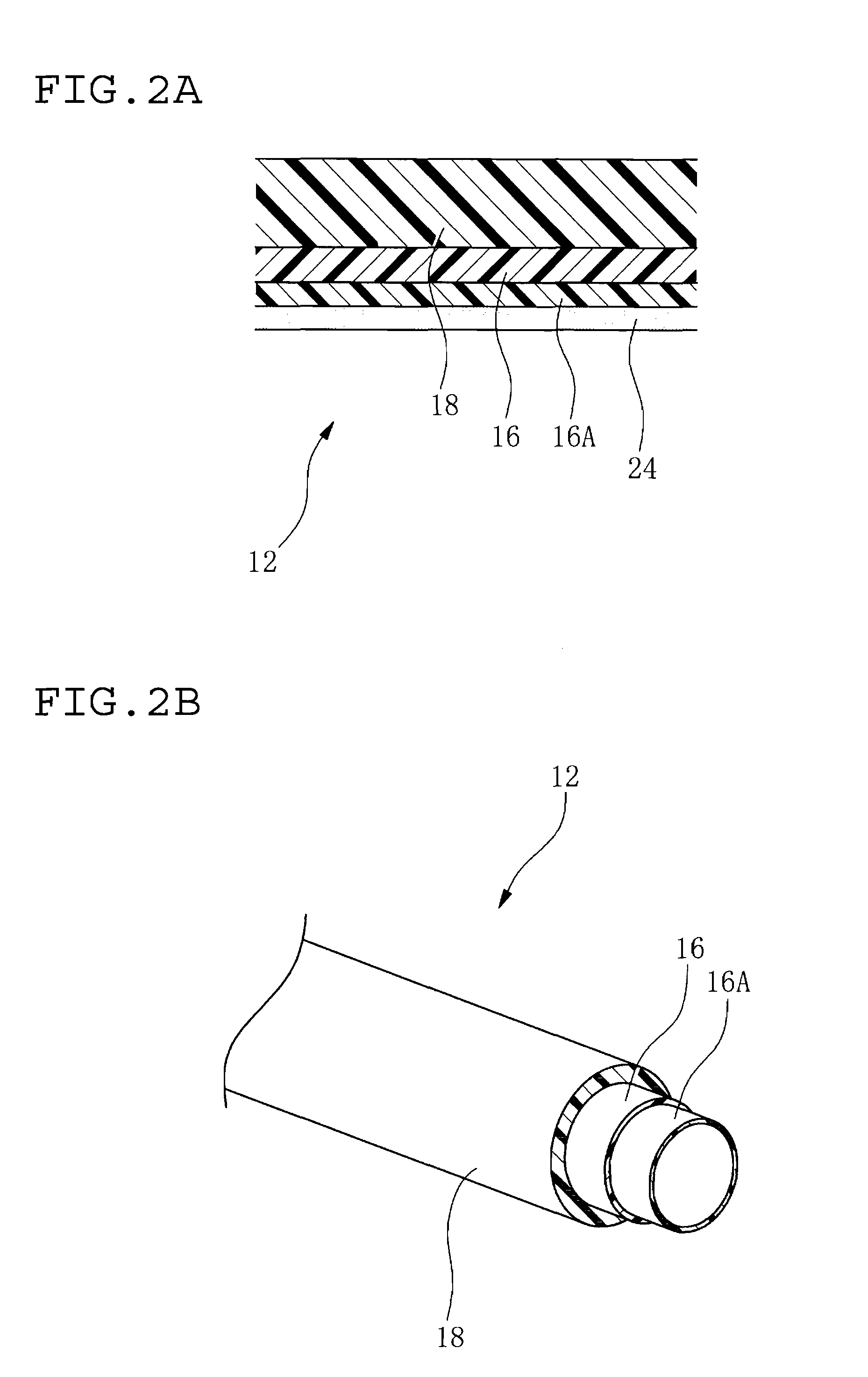
[0097]As shown in FIGS. 1B, 2A and 2B, the hose 12 has a multilayer structure including an innermost layer 16 made of ETFE, and a resin layer 18 made of PA12 on an outer side of the innermost layer 16.

[0098]Here, an inner periphery portion of the innermost layer 16 of ETFE is a conductive layer 16A. That is, the conductive layer 16A defines an inner surface layer of the innermost layer 16, and the whole of the innermost layer 16 including the conductive layer 16A is made of the same resin material (here, ETFE).

[0099]Meantime, as shown in FIG. 2C, the multilayer structure of the hose 12 may not includ...


PUM

PropertyMeasurementUnit
Pressureaaaaaaaaaa
Diameteraaaaaaaaaa
Melting pointaaaaaaaaaa

Abstract

In a method for producing a hose with a sealing layer, a hose body having a resin innermost layer is prepared, a rod-like core member is disposed through a center portion of a hollow interior of a connecting portion of the hose body so as to occupy the center portion, and the plasma gas is fed and distributed in an interior of an innermost layer of the connecting portion to modify an inner surface of the innermost layer. Then, the sealing layer is formed on the inner surface by coating an elastic material for the sealing layer on the inner surface of the connecting portion.

Description

1. FIELD OF THE INVENTION [0001]The present invention relates to a method for producing a hose with a resin layer defining an innermost layer, specifically, a hose with a sealing layer that is formed from an elastic material on an inner surface of a connecting portion of an end portion of the hose. The hose is suitable for conveying carbon hydride such as gasoline, light oil, compressed natural gas and liquefied petroleum gas, hydrogen, dimethyl ether, alcohol, warm water or a refrigerant for an air conditioner, etc.2. DESCRIPTION OF THE RELATED ART [0002]Conventionally, a hose with an innermost layer of a resin layer has been used for piping in vehicles.[0003]For example, a hose with an innermost layer of a fluorine resin has been used for a fuel conveying hose of a motor vehicle.[0004]The fuel conveying hose can be provided with enhanced gasoline-permeation resistance by including an innermost layer of such fluorine resin layer.[0005]And, for connecting this type of the hose to a ...

Claims


Application Information

Patent Timeline
IPC IPC(8): C23C16/513
CPCB29C59/103B29C59/142Y10T428/1352Y10T428/1393Y10T428/139B29C2059/145
Inventor TAKIMOTO, YORIHIRO
Owner TOKAI RUBBER IND LTD
Why Eureka
Eureka Blog
Learn More