Light output sticker

a technology of output sticker and light output, which is applied in the direction of lighting support device, lighting and heating apparatus, lighting elements, etc., can solve the problems of affecting the appearance of the surface when turned, the layout of the led cannot be customized by the user, and the cost of production of led glass products is high

Inactive Publication Date: 2012-07-12
KONINKLIJKE PHILIPS ELECTRONICS NV
View PDF6 Cites 11 Cited by
  • Summary
  • Abstract
  • Description
  • Claims
  • Application Information

AI Technical Summary

Benefits of technology

[0029]In one embodiment the surface of the sticker is made to create an etched glass appearance. ...

Problems solved by technology

A problem with such devices is that they detract from the appearance of the surface when they are turned off.
There are however several problems with current LED in glass products:
(i) The layout of the LEDs cannot be customized by the user, because otherwise the production of the LED in glass product becomes very expensive.
This means th...

Method used


Image

  • Light output sticker
  • Light output sticker
  • Light output sticker

Examples


first embodiment

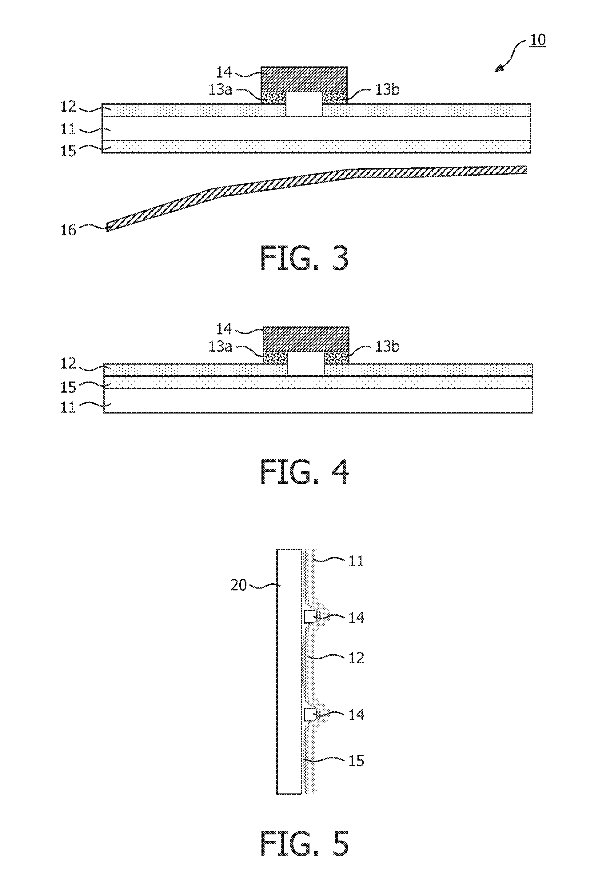
[0052]sticker 10 according to the present invention is shown in FIG. 3.

[0053]The first embodiment of sticker 10 comprises a flexible transparent strip 11 in the form of a foil, for example a plastic (PE, PP, PVC, PMMA) or rubber. The thickness is less than 3 mm, but preferably less than 1 mm, or even less than 0.5 mm. The area depends on the surface to which it will be applied, with dimensions ranging from a few cm2, to more than 1 m2, or even 10 m2. An at least semi-transparent conductive layer 12 is provided, onto which LEDs 14 are mounted (for example with connections 13a and 13b which may comprise a conductive glue or solder). Furthermore, the transparent strip 11 also comprises a transparent self-adhesive layer 15, which may be used to adhere the strip to for example a sheet of glass.

[0054]The self-adhesive layer can be any known self-adhesive layer, for example as used for the etch glass stickers.

[0055]A removable release liner 16 is provided, which is removed in order to expo...

second embodiment

[0057]In FIG. 3, the adhesive layer 15 is opposite from the location of the LEDs. However, in a second embodiment shown in FIGS. 4 and 5, the adhesive layer 15 is on the same side as the LEDs. The advantage of this embodiment is that after adhering the strip to for example a glass window, the LED is protected between this glass and the foil 11. It is noted that the conductor lines defined by layer 12 are narrow lines, so that nearly all of the adhesive layer is exposed to the upper surface of the sticker (this cannot be seen from FIG. 4).

[0058]FIG. 4 shows the structure and FIG. 5 shows the arrangement adhered to a glass panel 20.

[0059]Alternatively, the adhesive layer can be provided on top of the conductor arrangement, especially when a transparent conductive material such as ITO is used. In that case the sticker comprises for example a transparent substrate 11 with a patterned ITO layer 12 that is provided with LEDs 14, and the ITO layer+LEDs is coated with an adhesive layer 15 o...

third embodiment

[0060]In a third embodiment shown in FIG. 6, the LEDs are embedded in the foil 11. The LEDs 14 and the conductor arrangement (12 and 13a,13b) are both also embedded inside the foil 11.


PUM


Abstract

A light output sticker (10) comprises a flexible transparent substrate arrangement (11). A plurality of light source devices (14) are provided on or in the flexible substrate arrangement (11). A conductor arrangement (12) comprises conductor lines which connect to the light source devices. An adhesive layer (15) and release liner (16) are provided for attaching the sticker to an external substrate. The applied sticker is substantially transparent. The sticker of the invention avoids the need to embed the LEDs in a glass structure during the manufacturing of the glass. Instead, the LEDs are part of the transparent sticker, which can be added to a glass (or other material) substrate after manufacture of both the sticker and the glass (or other) material to which it is to be attached.

Description

FIELD OF THE INVENTION [0001]This invention relates to a light output sticker, in particular using discrete light source devices provided on an adhesive backing for application to a product. The invention also relates to a lighting system using the sticker and an installation method.BACKGROUND OF THE INVENTION [0002]An adhesive LED ribbon is a known device for providing lighting effects to a surface. Such devices comprise a strip of material on which LEDs are mounted, with electrical connections running along the strip of material. A problem with such devices is that they detract from the appearance of the surface when they are turned off.[0003]Another known device is a so-called “LED in glass” device. An example is shown in FIG. 1. Typically a glass plate is used, with a transparent conductive coating (for example ITO) forming electrodes. The conductive coating is patterned in order to make the electrodes, that are connected to a semiconductor LED device. The assembly is completed ...

Claims


Application Information

Patent Timeline
IPC IPC(8): F21V33/00
CPCF21V21/0808F21S4/005F21S4/22
Inventor VAN HERPEN, MAARTEN MARINUS JHANNES WILHELMMAANDONKS, ARNOLDUS JOHANNES LUCAS MARIADEKKER, TIM
Owner KONINKLIJKE PHILIPS ELECTRONICS NV
Why Eureka
Try Eureka