Unlock instant, AI-driven research and patent intelligence for your innovation.
Image forming apparatus
Inactive Publication Date: 2012-07-12
CANON KK
View PDF0 Cites 4 Cited by
Summary
Abstract
Description
Claims
Application Information
AI Technical Summary
This helps you quickly interpret patents by identifying the three key elements:
Problems solved by technology
Method used
Benefits of technology
Benefits of technology
[0012]A principal object of the present invention is to provide an image forming apparatus capable of suppressing an non-uniform abrasion image, such as a vertical stripe image or a stepwise non-uniform density image due to abrasion of a photosensitive layer, generated in the latter half of a lifetime of an image bearing member while suppressing a stripe image and image blur due to rotational load fluctuation of the image bearing member.
Problems solved by technology
Further, it is known that this causes an occurrence of a stripe on an image or image blur (density fluctuation or the like) during subsequent image formation.
However, in this case, a retracting mechanism is costly and in addition, it is difficult to ensure accuracy of the contact state when the cleaning blade is contacted again in after being retracted.
For this reason, the retraction of the cleaning blade leads to defective cleaning and by extension to deterioration of an image quality.
Further, when the cleaning blade contacts the image bearing member again, there arises such a problem that the cleaning blade is required to contact again an image bearing member area, which has been cleaned before the retraction, in order not to create an uncleaned area.
As a result, the fine powder toner and the external additive which stagnate at the cleaning blade edge portion are dispersed, so that degrees of the stripe and the image blur due to rotational load fluctuation of the image bearing member are reduced with reliability.
Therefore, this problem is conspicuous in the latter half of a lifetime of the image bearing member in which the layer thickness of the photosensitive layer becomes thin.
Method used
Image
Click on the blue label to locate the original text in one second.
Reading with bidirectional positioning of images and text.
Examples
embodiment 1
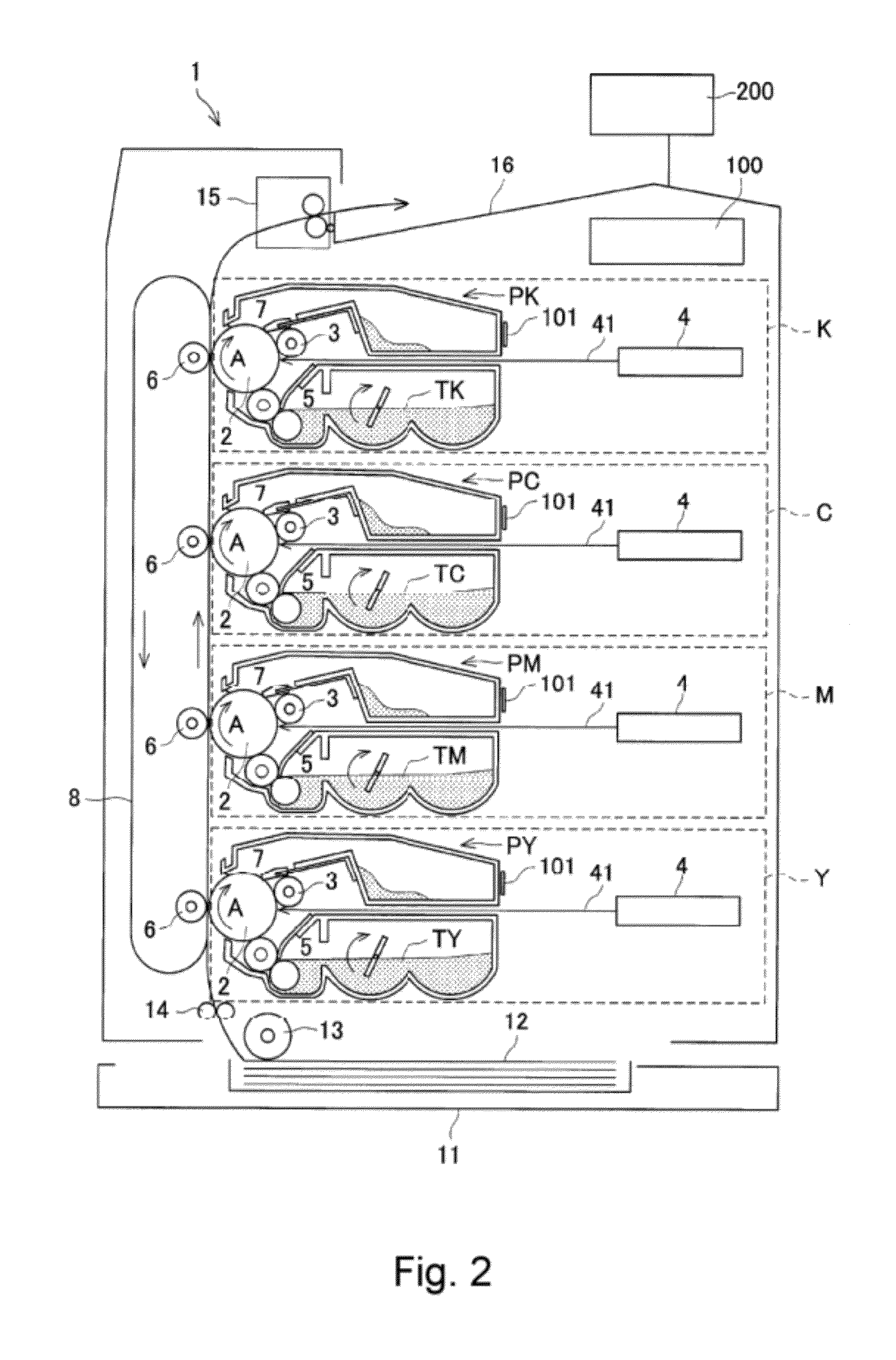
[0027]FIG. 2 is a schematic illustration of an image forming apparatus in this embodiment. This image forming apparatus 1 is a four color-based full-color image forming apparatus (multi-color image forming apparatus) which uses an electrophotographic process and has a vertical tandem constitution (in-line constitution).
[0028]Inside the image forming apparatus 1, first to fourth (four) image forming stations Y, M, C and K for forming toner images of yellow, magenta, cyan and black, respectively, are arranged in parallel from a lower side to an upper side (the vertical tandem constitution).
[0029]The respective image forming stations Y, M, C and K are the same electrophotographic process mechanism except that the colors of the toner images to be formed are different from each other. That is, each of the image forming stations includes a drum-like electrophotographic photosensitive member 2 as the image bearing member (hereinafter referred to as a photosensitive drum 2), a charging roll...
embodiment 2
[0086]A constitution in this embodiment will be described with reference to FIG. 7. FIG. 7 is an enlarged schematic view of the process cartridge an the toner cartridge.
[0087]This embodiment is characterized in that each of a P cartridge and a T cartridge, which are described below, in each of the image forming stations Y, M, C and K is provided detachably mountable to the main assembly of the image forming apparatus 1. The perform cartridge is the process cartridge (PY, PM, PC, PK) which is prepared by collectively assembling five process devices of the photosensitive drum 2, the charging roller 3, the developing device 5, the cleaning device 7 and a non-volatile memory 101P into a unit which is detachably mountable to the main assembly. The T cartridge is a toner cartridge (PTY, PTM, PTM, PTK) which is prepared by integrally assembling the toner container 49 (developing container) in which the developer is accommodated and a non-volatile memory 101T in which fresh product informat...
embodiment 3
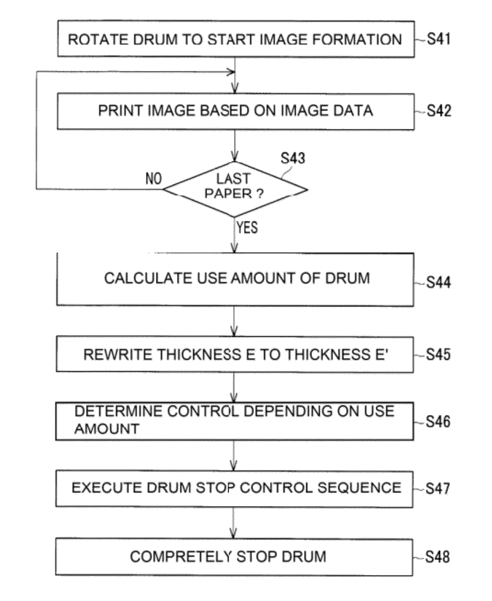
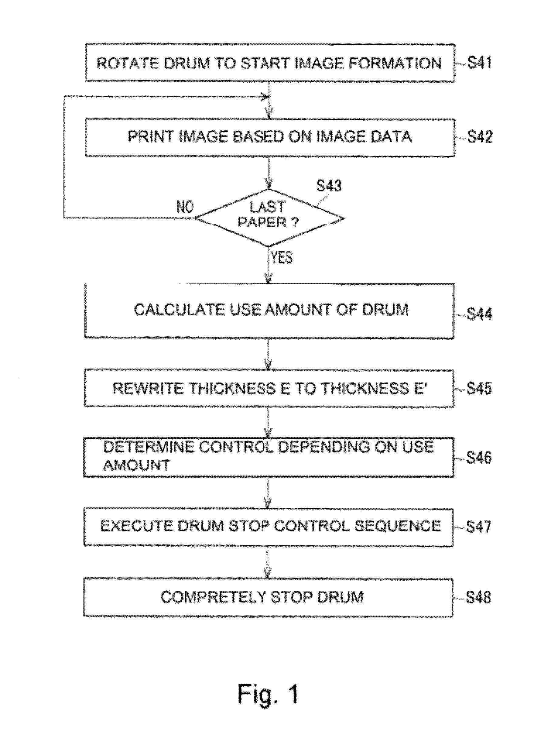
[0108]In this embodiment, depending on the remaining amount D of the photosensitive drum 2, the number of rotations of the intermittent normal rotation performed after the stop of the photosensitive drum and the rotation amount of the reverse rotation were controlled. Other constitutions are the same as those in Embodiment 1.
(Specific Control Method in Constitution in Embodiment 3)
[0109]In this embodiment, the control of the normal rotation and the reverse rotation in the photosensitive drum stop control sequence is effected depending on the remaining amount D of the photosensitive drum 2. In Embodiment 3, in the range of the photosensitive drum remaining amount D from 100% to 55% described in [2. Specific control flow] in Embodiment 1, the intermittent normal rotation is performed 5 times as movement of 1 mm per 5 sec and the reverse rotation is performed as movement of 5 mm after a lapse of 5 sec from the stop of the intermittent normal rotation. In the range from 54% to 0%, the i...
PUM
Abstract
An image forming apparatus includes an image bearing member for bearing a developer image; a driving portion for rotationally driving the image bearing member; a developing device for developing an electrostatic latent image on the image bearing member into the developer image; a cleaning blade, slidably contacting the image bearing member which is rotated, for removing from the image bearing member a developer remaining on the image bearing member after transfer of the developer image; a controller capable of executing a stop operation of the image bearing member in which the image bearing member is, after being temporarily stopped at the time of an end of an image forming operation, rotated in the same direction as that during the image forming operation and then is rotated in a direction opposite to that during the image forming operation; and a predicting portion for predicting a remaining usable lifetime of the image bearing member. In the stop operation of the image bearing member after the remaining usable lifetime is below a threshold, the controller controls an amount of rotation in the direction opposite to that during the image forming operation so as to be smaller than the amount of rotation before the remaining usable lifetime is below the threshold.
Description
FIELD OF THE INVENTION AND RELATED ART[0001]The present invention relates to an image forming apparatus, such as a copyingmachine or a printer in which image formation is effected by a transfer type electrophotographic process, an electrostatic recording process, and the like. Particularly, the present invention relates to the image forming apparatus in which a blade cleaning device is used as a cleaning device for an image bearing member such as an electrophotographic photosensitive member or an electrostatic recording dielectric member.[0002]After a developer image on the image bearing member is transferred onto a recording material such as paper, the developer remains on the image bearing member in some cases. For example, in the image forming apparatus of an ordinary transfer type using the electrophotographic process represented by a Carlson process. As the cleaning device for removing such a transfer residual developer (hereinafter referred to as a transfer residual toner), t...
Claims
Application Information
Patent Timeline
Application Date:The date an application was filed.
Publication Date:The date a patent or application was officially published.
First Publication Date:The earliest publication date of a patent with the same application number.
Issue Date:Publication date of the patent grant document.
PCT Entry Date:The Entry date of PCT National Phase.
Estimated Expiry Date:The statutory expiry date of a patent right according to the Patent Law, and it is the longest term of protection that the patent right can achieve without the termination of the patent right due to other reasons(Term extension factor has been taken into account ).
Invalid Date:Actual expiry date is based on effective date or publication date of legal transaction data of invalid patent.

