Portable Vehicle Barrier

Inactive Publication Date: 2012-07-12
SECURITY SOLUTIONS INT
View PDF9 Cites 52 Cited by
  • Summary
  • Abstract
  • Description
  • Claims
  • Application Information

AI Technical Summary

Problems solved by technology

However, existing barriers often sacrifice effectiveness for ease of use or vice versa.
Spike strips, while easy to deploy, merely puncture a vehicle's tires, aft

Method used


Image

  • Portable Vehicle Barrier
  • Portable Vehicle Barrier
  • Portable Vehicle Barrier

Examples


Embodiment Construction

[0012]All illustrations of the drawings are for the purpose of describing selected versions of the present invention and are not intended to limit the scope of the present invention.

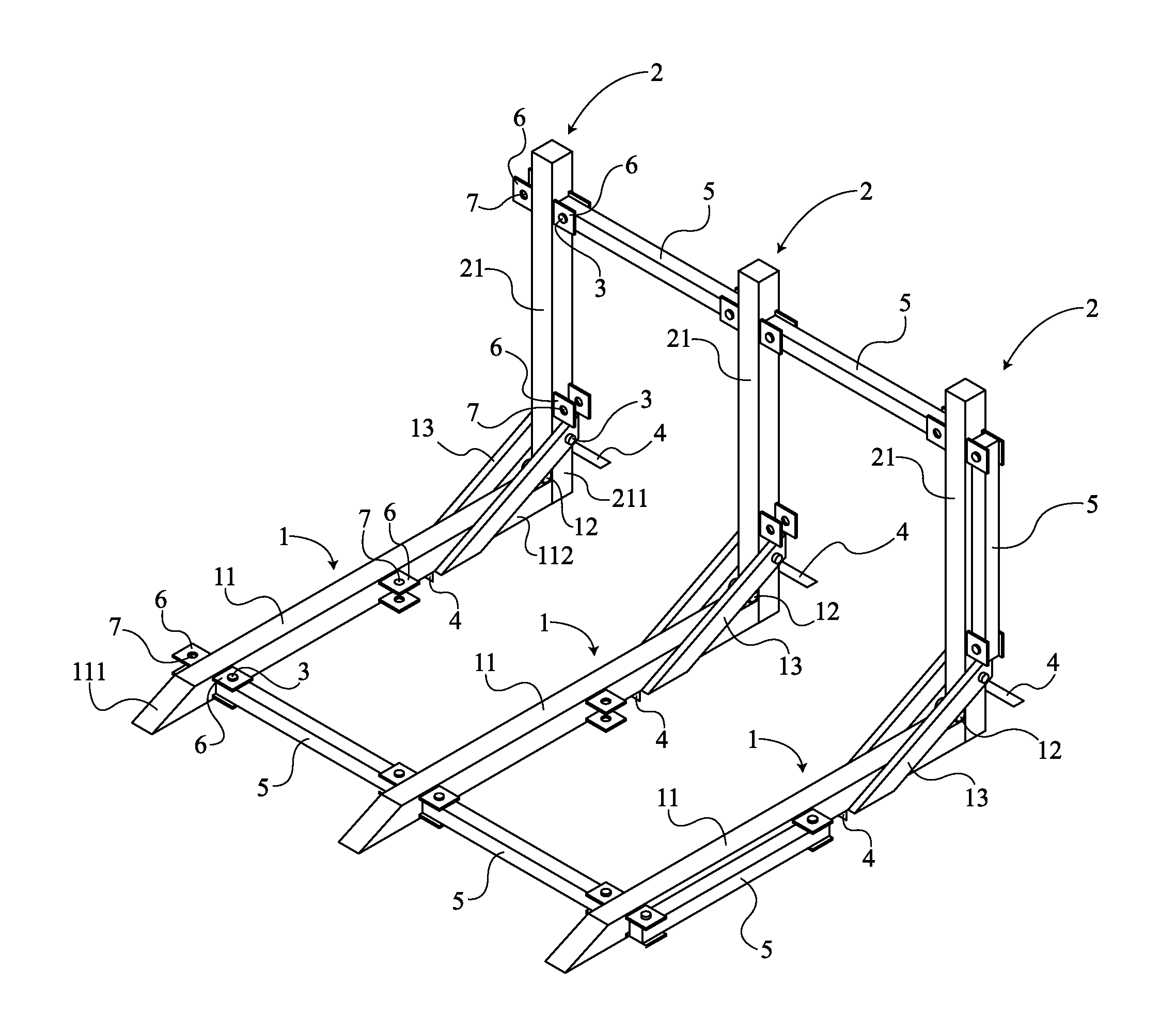
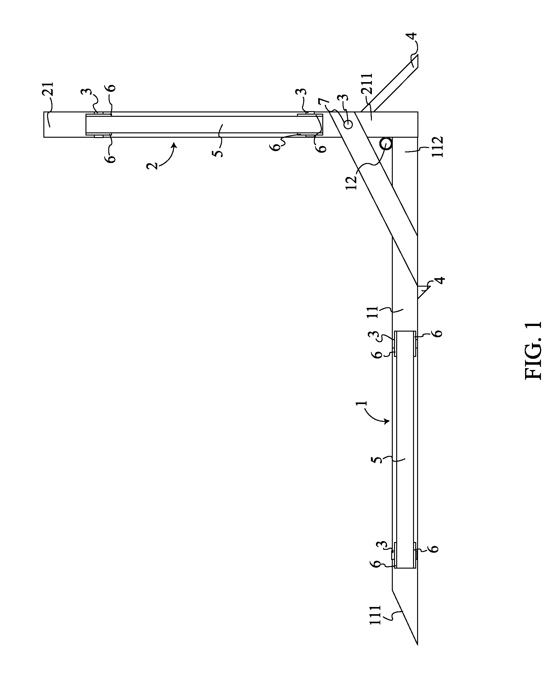
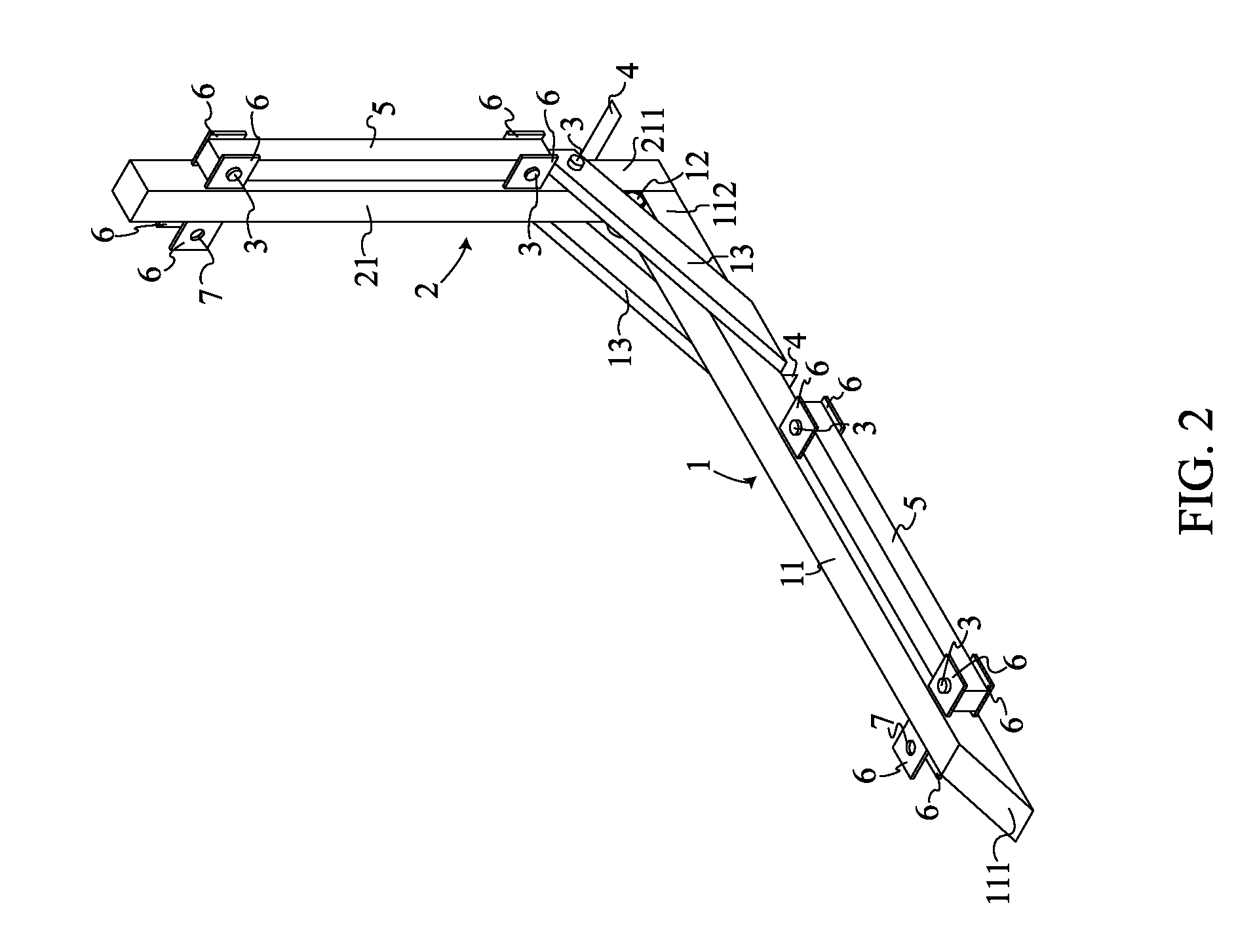
[0013]As can be seen in FIGS. 1,2,3,4,5, and 6, the present invention comprises a front base 1, a rear base 2, a plurality of pins 3, a plurality of spikes 4, a plurality of folding arms 5, and a plurality of arm housings 6. The front base 1 (which allows the present invention to engage oncoming vehicles) and rear base 2 (which provides the initial force to halt oncoming vehicles) are positioned perpendicular to each other. The folding arms 5 are positioned adjacent to both the front base 1 and rear base 2, and rotate out to connect individual barriers. The folding arms 5 are secured to the arm housings 6 which are attached to both the front base 1 and rear base 2. The spikes 4 are located underneath the front base 1 and angled down from the rear base 2. The spikes 4 serve to dig into the ground, slowing...


PUM


Abstract

The present invention is a portable vehicle barrier, which is used to easily and effectively block vehicle access to restricted areas. The present invention comprises a front base, a rear base, spikes, and multiple folding arms. The folding arms are used to connect individual barriers to form a larger barrier so they can block small or large areas as needed. The spikes drive into the ground slowing oncoming vehicles and eventually stopping them as the barrier cantilevers intruding vehicles on the front base. For storage and transportation the folding arms can be folded to rest alongside the front base and rear base, while the rear base can be folded to rest atop the front base. A plurality of arm housings are located along the front and rear base, and are use to secure the folding arms in the deployed or storage states.

Description

[0001]The current application claims a priority to the U.S. Provisional Patent application Ser. No. 61 / 431,651 filed on Jan. 11, 2011.FIELD OF THE INVENTION[0002]The present invention relates generally to a portable device for barricading restricted areas from vehicular access.BACKGROUND OF THE INVENTION[0003]To cordon off restricted areas, government and private entities use a variety of barriers, such as concrete barriers and spike strips. However, existing barriers often sacrifice effectiveness for ease of use or vice versa. Spike strips, while easy to deploy, merely puncture a vehicle's tires, after which it can still travel for some distance. Concrete barriers are much more effective in stopping vehicles but are also much more difficult to deploy and move. The object of the present invention is to introduce a barrier that is easy to assemble, deploy, and transport, while still being an effective barrier. The present invention is a user friendly anti-ramming device which is ligh...

Claims


Application Information

Patent Timeline
IPC IPC(8): E01F13/00
CPCE01F13/12
Inventor MORE, UZIMORGENSTERN, HENRY
Owner SECURITY SOLUTIONS INT
Why Eureka
Try Eureka