
Laryngoscope

a technology of laryngoscope and otoscope, which is applied in the field of laryngoscope, can solve the problems of limited use of mccoy laryngoscope, and achieve the effects of saving the lives of many patients, reducing the burden on patients, and shrinking the muscles around the epiglottis

Inactive Publication Date: 2012-07-12
UNIV OKAYAMA
View PDF7 Cites 9 Cited by
  • Summary
  • Abstract
  • Description
  • Claims
  • Application Information

AI Technical Summary

Benefits of technology

[0016]In the laryngoscope of the invention, which includes the first electrode and the second electrode, a low frequency current flows between the first electrode and the second electrode so that muscles around an epiglottis are shrunken by stimulation due to this low frequency current thus lifting the epiglottis. Accordingly, an operator can carry out the tracheal intubation surely. Further, also in a case where a life guard cannot carry out the tracheal intubation (a case where the life guard cannot visually recognize the trachea) conventionally, the life guard can carry out the tracheal intubation so that lives of many patients can be saved.
[0017]When a pulse current having a frequency of 10 to 100 Hz and an electric current value of 10 mA to 100 mA is used as the low frequency current, the laryngeal exposure can be carried out without imposing an excessive burden on a patient.
[0018]When the first electrode is arranged on the distal end portion of the blade by way of an insulating cover which covers at least the distal end portion of the blade, the electrode can be arranged on the distal end portion of the blade regardless of the material of the blade. Accordingly, the laryngeal exposure using a low frequency current can be carried out using any kind of blade.
[0019]By adhering the second electrode to the skin surface in the vicinity of an epiglottis of a patient and by allowing a low frequency current to flow between the first electrode and the second electrode, it is possible to shrink muscles around the epiglottis by such a low frequency current so that the epiglottis can be lifted.
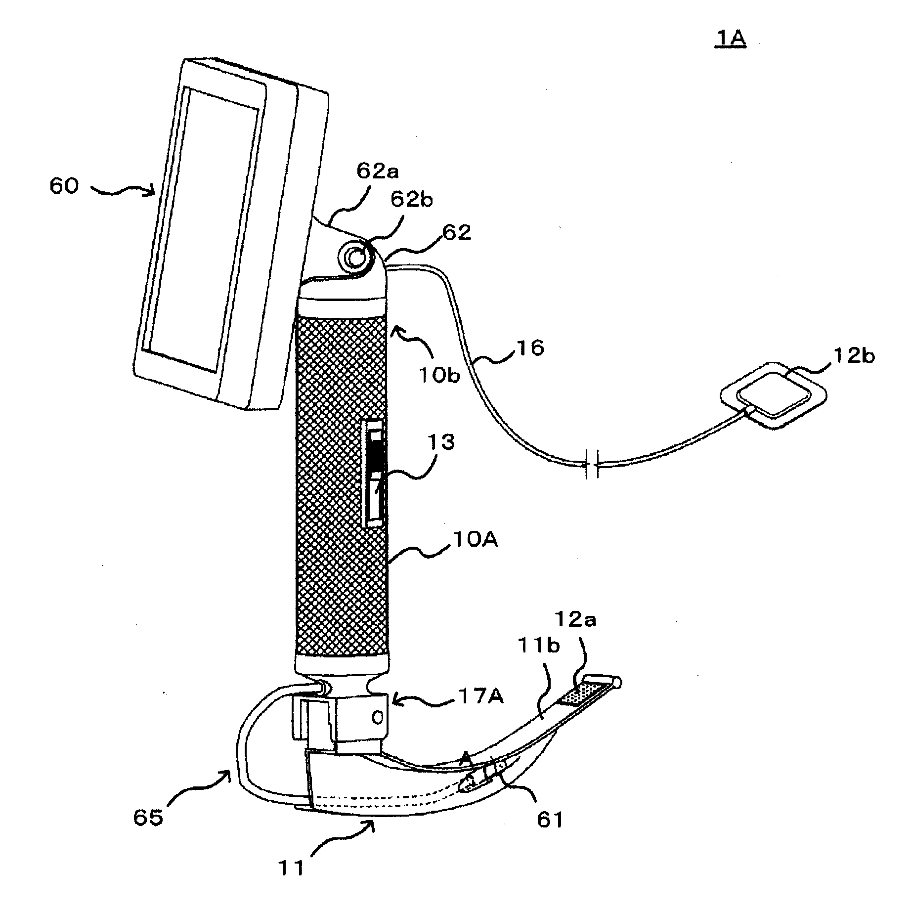
[0020]When an imaging part is mounted on the distal end portion of the blade, a display part is tiltably mounted on a proximal end of the handle, and an image picked up by the imaging part is displayed on the display part, in carrying out the tracheal intubation, an operator can visually recognize a trachea inlet portion of a patient based on the image displayed on the display part. Accordingly, the operator can visually recognize the trachea inlet portion in a relaxed posture and hence, the operator can easily carry out the tracheal intubation.

Problems solved by technology

Accordingly, when tracheal intubation (insertion of a tube into a trachea from an oral cavity) is carried out in an emergency case such as stopping of respiration of a patient, an excessively large force is applied to the lever due to a tension of a doctor so that there may be a case where blood bleeds from a root portion of the epiglottis or the root portion swells when the excessively large force is applied resulting in a critical situation.
Accordingly, situations where the McCoy laryngoscope can be used are limited.
However, in this laryngoscope, the tracheal intubation is carried out while checking the inside of an oral cavity on a screen of the LCD monitor so that an operator cannot directly observe a trachea inlet portion.

Method used


Image

  • Laryngoscope
  • Laryngoscope
  • Laryngoscope

Examples


Embodiment Construction

[0031]Hereinafter, the mode for carrying out the present invention (hereinafter referred to as “embodiment”) is explained.

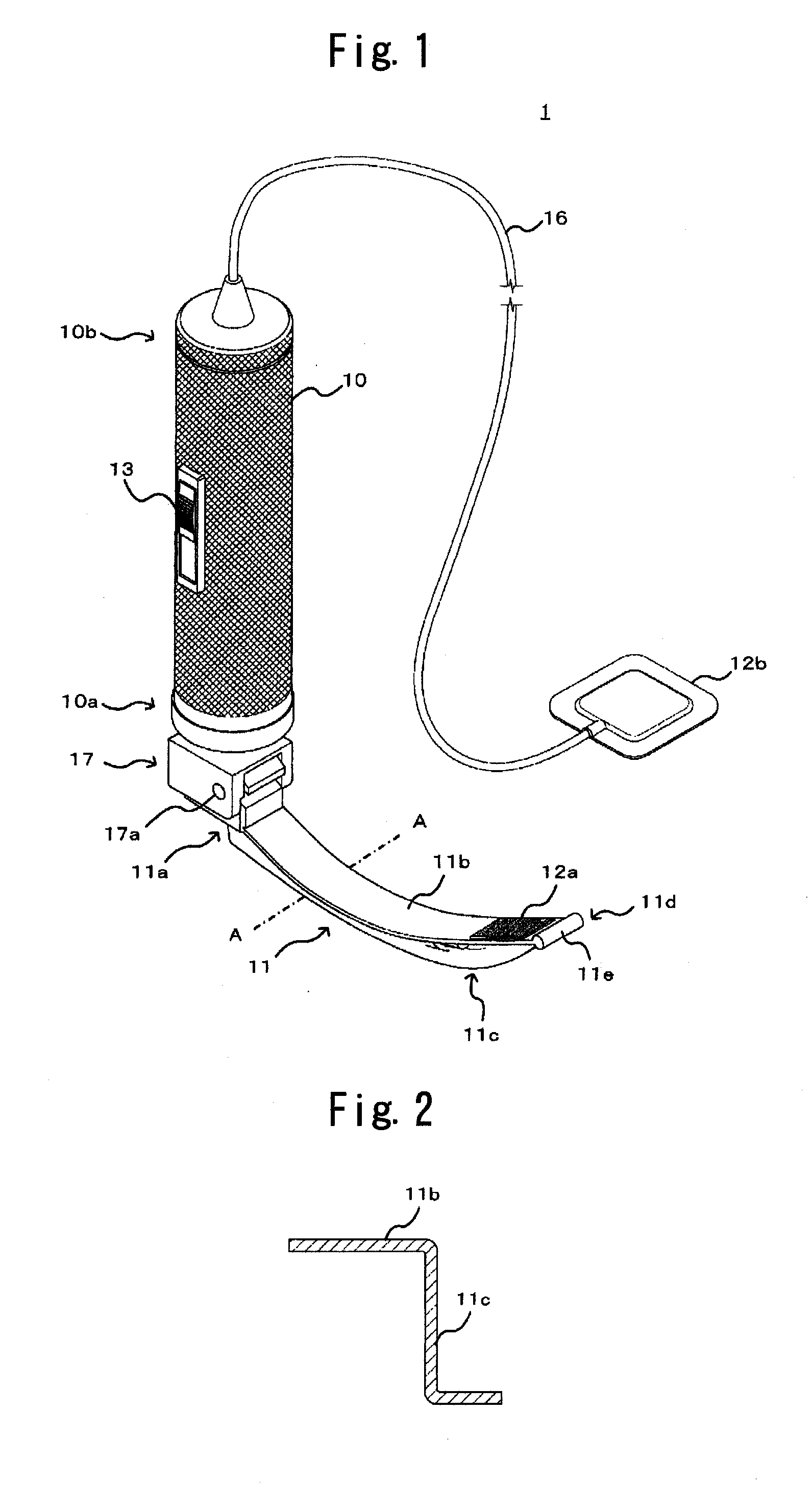
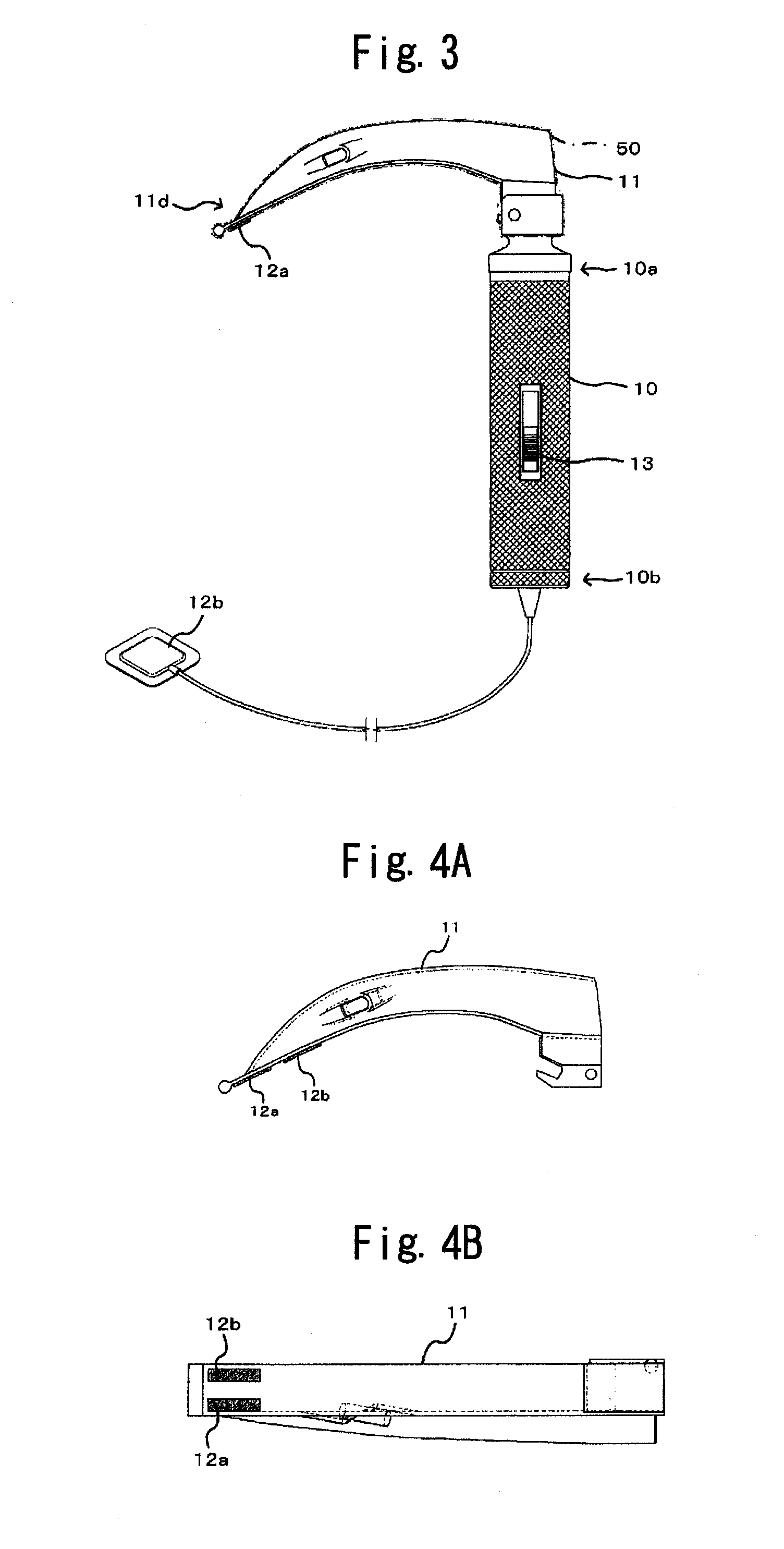
[0032]FIG. 1 is a perspective view showing the external appearance of a laryngoscope according to the embodiment, and FIG. 2 is a cross-sectional view taken along a line A-A in FIG. 1. As shown in FIG. 1, the laryngoscope 1 includes a handle 10 and a blade 11 which is mounted on the handle 10. On a contact surface formed on a distal end of the blade 11 which is brought into contact with a proximal end portion of an epiglottis, a first electrode 12a is mounted. As a constitutional element provided separate from a body of the laryngoscope 1, a second electrode 12b is arranged at a position where the second electrode 12b becomes electrically conductive with the first electrode 12a. A power source switch 13 is arranged on an outer peripheral surface of the handle 10, and a power source part 14 and a low frequency generating part 15 are arranged in the inside of the h...


PUM


Abstract

A laryngoscope is provided with which an operator can directly observe the trachea inlet portion of a patient easily by safely and surely lifting the epiglottis of the patient with a proximal end portion of a laryngoscope blade which is inserted in the mouth of the patient. The blade is connected to a distal end portion of a grippable handle, a first electrode is mounted on a distal end portion of the blade, and a second electrode is configured to adhere to a skin surface of the patient in the vicinity of the epiglottis, and a low frequency current is supplied to flow between the first electrode and the second electrode.

Description

BACKGROUND OF THE INVENTION[0001]The present invention relates to a laryngoscope, and more particularly to a laryngoscope which is used for enabling an operator to visually recognize a trachea inlet portion by lifting an epiglottis which is used in fields of anesthesia, emergency, an intensive care and the like.[0002]In fields of anesthesia, emergency, an intensive care field and the like, it has been practiced in general that a tube is inserted into a trachea from an oral cavity thus ensuring the clearing of an airway which is a passage of oxygen necessary for respiration (airway control).[0003]In carrying out the airway control, prior to the insertion of the tube, the treatment referred to as laryngeal exposure is carried out for enabling an operator to visually recognize a trachea inlet portion. That is, a lid portion referred to as an epiglottis is present in the trachea inlet portion and this epiglottis prevents food or drink from entering a trachea. In carrying out the airway ...

Claims


Application Information

Patent Timeline
IPC IPC(8): A61B1/267A61B1/04
CPCA61B1/267A61B1/00131A61B1/00087A61M16/0488A61M16/0495
Inventor TAKEDA, YOSHIMASAMORITA, KIYOSHIKOBAYASHI, TAKEHARU
Owner UNIV OKAYAMA
Learn More