Vehicle heat source control device and method for controlling vehicle heat source

a technology for controlling devices and heat sources, which is applied in vehicle heating/cooling devices, vehicle components, instruments, etc., can solve problems such as the inability to ensure the heat power necessary for heating, the inability to reduce the power wasted from the engine, and the inability to use how much and which heat sources. achieve the effect of reducing fuel consumption, reducing heat cost and minimizing supply of heat power

Inactive Publication Date: 2012-07-12
DENSO CORP
View PDF3 Cites 32 Cited by
  • Summary
  • Abstract
  • Description
  • Claims
  • Application Information

AI Technical Summary

Benefits of technology

[0008]The present invention is made in view of these actual circumstances, and the object of the present invention is to reduce a fuel quantity consumed to supply heat even in the case where an abnormal heat source is caused in a plurality of heat sources mounted in a vehicle.
[0009]According to an aspect of the present invention, a vehicle heat source control device configured to control heat supply from a plurality of heat sources equipped in a vehicle to a heat exchange part, the vehicle heat source control device comprises a request heat power calculation unit configured to calculate a request heat power, which is requested to the plurality of heat sources to supply to the heat exchange part. The vehicle heat source control device further comprises a heat cost calculation unit configured to calculate a relationship between a heat power supplied from each of the plurality of heat sources and a heat cost being a fuel quantity consumed to supply a unit heat power. The vehicle heat source control device further comprises an abnormal heat source detection unit configured to detect an abnormal heat source, which is incapable of normally supplying a heat power, from the plurality of heat sources. The vehicle heat source control device further comprises an abnormal heat power calculation unit configured to calculate an abnormal heat power, which is a heat power supplied from the abnormal heat source. The vehicle heat source control device further comprises a heat distribution determination unit configured to determine distribution of heat power supplied from the plurality of heat sources based on both: the relationship between the heat power supplied from each of the plurality of heat sources and the heat cost; and the abnormal heat power, such that: a sum total of the heat power supplied from the plurality of heat sources coincides with the request heat power; and the heat cost of all of the plurality of heat sources to supply the heat power is minimized.
[0010]According to another aspect of the present invention, a method for controlling heat supply from a plurality of heat sources equipped in a vehicle to a heat exchange part, the method comprises calculating a request heat power, which is requested to the plurality of heat sources to supply to the heat exchange part. The method further comprises calculating a relationship between a heat power supplied from each of the plurality of heat sources and a heat cost, which is a fuel quantity consumed to supply a unit heat power. The method further comprises detecting an abnormal heat source, which is incapable of normally supplying a heat power, from the plurality of heat sources. The method further comprises calculating an abnormal heat power being a heat power supplied from the abnormal heat source. The method further comprises determining distribution of heat power supplied from the plurality of heat sources based on both: the relationship between the heat power supplied from each of the plurality of heat sources and the heat cost; and the abnormal heat power, such that: a sum total of the heat power supplied from the plurality of heat sources coincides with the request heat power; and the heat cost of all of the plurality of heat sources to supply the heat power is minimized.

Problems solved by technology

However, in the low fuel consumption vehicle taken as an example, the heat power wasted from the engine is reduced because of an idling stop and an improvement in the efficiency of the engine itself, which causes a possibility that a heat power necessary for heating cannot be ensured only by the waste heat from the engine.
By the way, the construction described in Japanese Patent Publication No. 3704788 includes a plurality of heat sources used for heating the interior of the cabin and hence presents a problem how much and which of the heat sources is to be used from the viewpoint of efficient use of energy.
However, the construction described in Japanese Patent Publication No. 3704788 does not establish a principle of supplying heat from the plurality of heat sources but still has plenty room for improvement.
Moreover, in the case where an abnormal heat source which cannot properly supply heat is caused in the plurality of heat sources, how to supply the heat from the plurality of heat sources including the abnormal heat source becomes a problem.

Method used


Image

  • Vehicle heat source control device and method for controlling vehicle heat source
  • Vehicle heat source control device and method for controlling vehicle heat source
  • Vehicle heat source control device and method for controlling vehicle heat source

Examples


Embodiment Construction

[0026]Hereinafter, an embodiment will be described with reference to the drawings.

[0027]The present embodiment is embodied as a system for controlling heat supply from a plurality of heat sources mounted in a vehicle to a heat exchange part and electric power supply from a plurality of power sources to a plurality of electric loads at the time of heating the interior of a cabin.

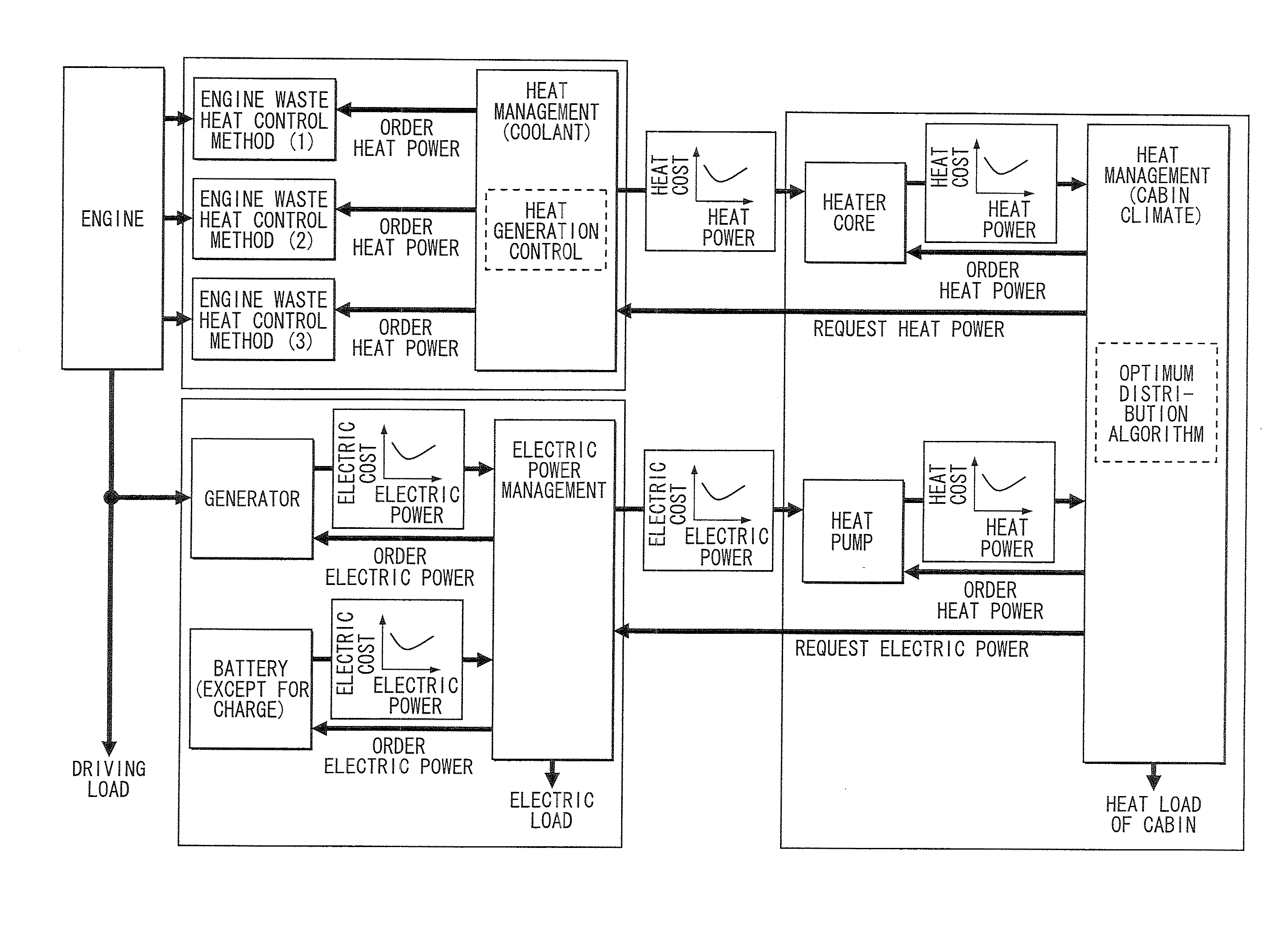
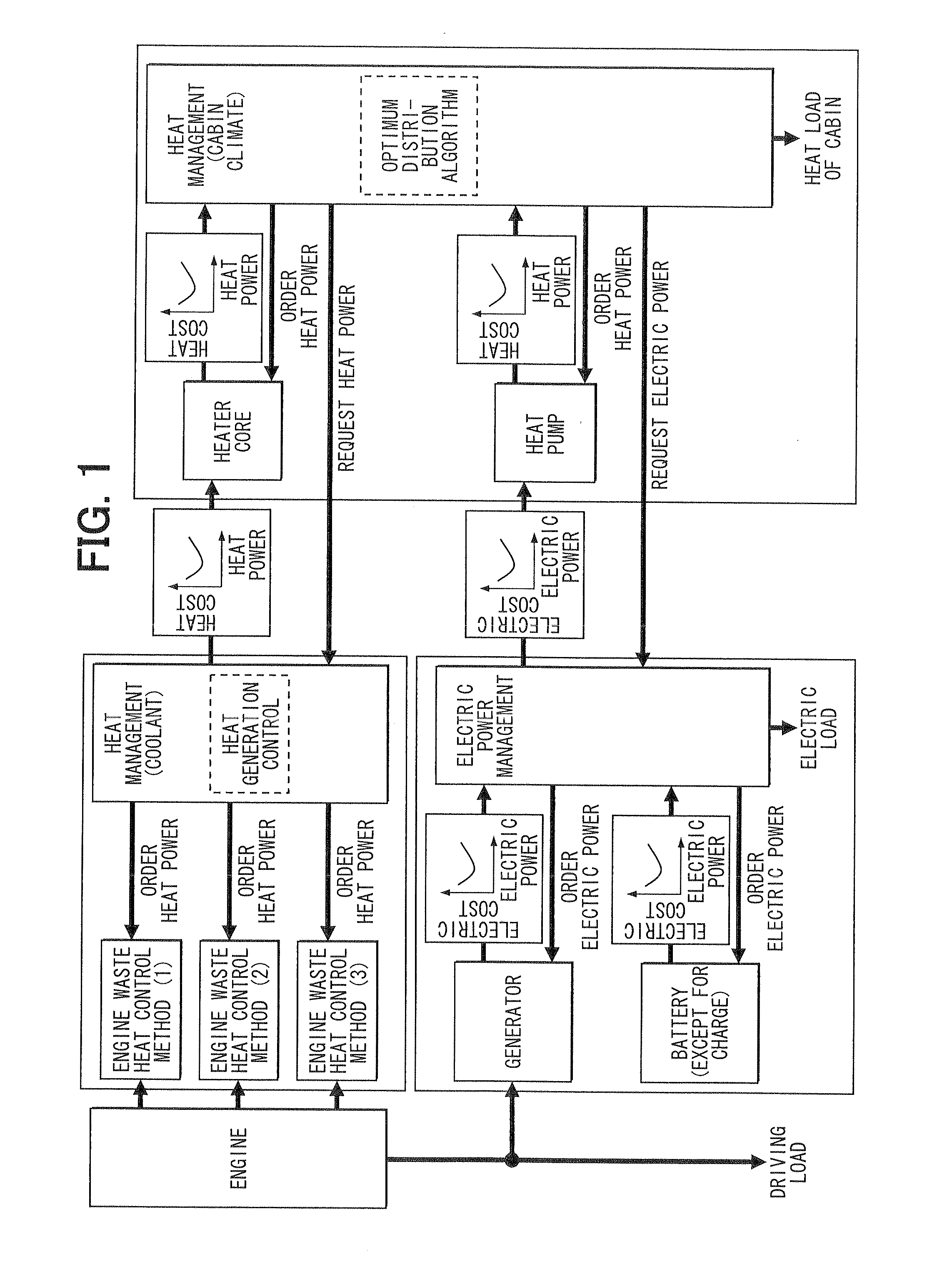
[0028]The outline of control of the heat supply and the electric power supply in this system will be shown in FIG. 1. As shown in the drawing, in this system, the distribution of heat power to be supplied from the plurality of heat sources (supply load distribution of the respective heat sources) is determined in such a way that fuel consumed so as to supply heat to the respective heat exchange parts from a plurality of heat sources for heating is minimized.

[0029]As for the plurality of heat sources, the present system is provided with the heat power of coolant, such as cooling water, of an engine and a heat ...


PUM


Abstract

A request heat calculation unit calculates a request heat power requested to heat sources to supply. A heat cost calculation unit calculates a relationship between a heat power supplied from each of the heat sources and a heat cost, which is a fuel quantity consumed to supply a unit heat power. An abnormal source detection unit detects an abnormal heat source, which cannot normally supply a heat power, from the heat sources. An abnormal heat calculation unit calculates an abnormal heat power supplied from the abnormal heat source. A determination unit determines distribution of heat power supplied from the heat sources based on both the relationship and the abnormal heat power, such that a sum of the heat power supplied from the heat sources coincides with the request heat power, and the heat cost of all the heat sources is minimized.

Description

CROSS REFERENCE TO RELATED APPLICATIONS[0001]This application is based on Japanese Patent Application No. 2011-944 filed on Jan. 6, 2011, the contents of which are incorporated in their entirely herein by reference.FIELD OF THE INVENTION[0002]The present invention relates to a device for controlling heat supply from heat sources of a vehicle. The present invention further relates to a method for controlling the heat supply from heat sources.BACKGROUND OF THE INVENTION[0003]In recent years, various technologies have been developed from a viewpoint of reducing the quantity of fuel consumed in a vehicle. For example, there have been developed a hybrid vehicle, which has an electric motor as a main unit mounted in a vehicle in addition to an engine, and an idling stop system for automatically stopping an engine when a vehicle stops.[0004]In general, in the heating of the interior of a cabin, heat wasted to the coolant and the rest from an engine is utilized. However, in the low fuel con...

Claims


Application Information

Patent Timeline
Patent Type & Authority Applications(United States)
IPC IPC(8): B60H1/22
CPCB60H1/00735B60H1/00899B60H1/00764B60H1/0073
Inventor OKAMOTO, TSUYOSHITASHIRO, TSUTOMUTANI, KEISUKE
Owner DENSO CORP
Why Eureka
Try Eureka