
Hand dispenser for stretch wrap

Active Publication Date: 2012-07-19
BROADWAY HLDG I
View PDF4 Cites 20 Cited by
  • Summary
  • Abstract
  • Description
  • Claims
  • Application Information

AI Technical Summary

Benefits of technology

[0024]The outer mold is made of a material with a high coefficient of friction compared to the extended core of the film wrap. The inner mold has a lower coefficient of friction compared to the outer mold. When squeezed the outer mold touches the extended core through the slots of the inner mold. This causes additional friction which, when increasing the amount of force applied to the outer mold, slows down and stops the extended core from spinning and dispensing film. The low coefficient of friction between the inner mold and the extended core allows the extended core to turn and release the film when the squeezing force is reduced and the outer mold no longer touches the core.
[0041]It is an object of the present invention for the extensions of the inner mold to be flexible. This allows the ridges of the inner mold to snap into the groove of the extended core.

Problems solved by technology

This causes additional friction which, when increasing the amount of force applied to the outer mold, slows down and stops the extended core from spinning and dispensing film.

Method used


Image

  • Hand dispenser for stretch wrap
  • Hand dispenser for stretch wrap
  • Hand dispenser for stretch wrap

Examples


Embodiment Construction

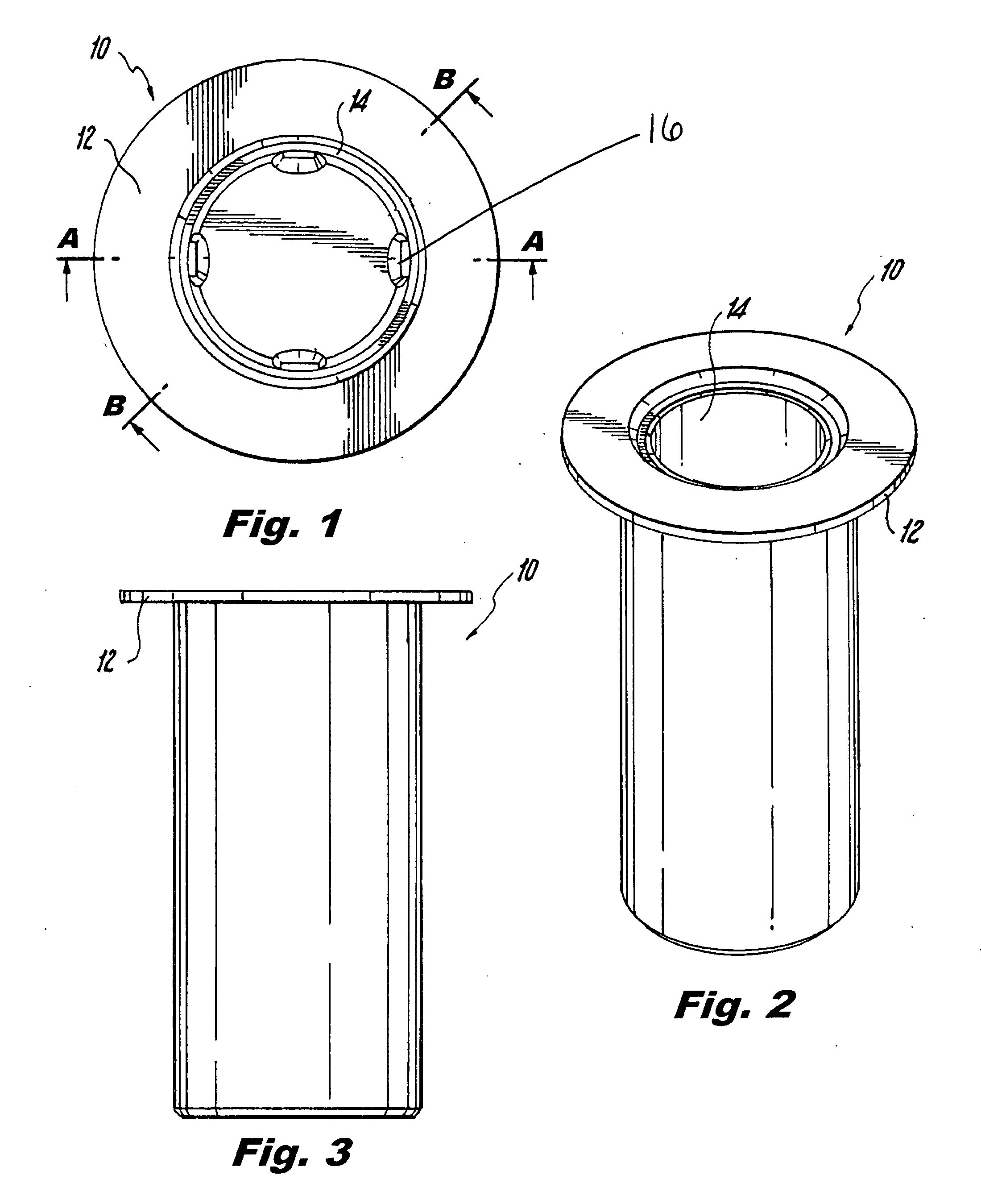
[0058]FIG. 1 is a top view of a film dispenser. The film dispenser 10 has a collar 12, an inner mold 14 and an outer mold 16.

[0059]FIG. 2 shows the side view of the film dispenser 10 having a collar 12.

[0060]FIG. 3 shows a side view of the film dispenser 10 having a collar 12.

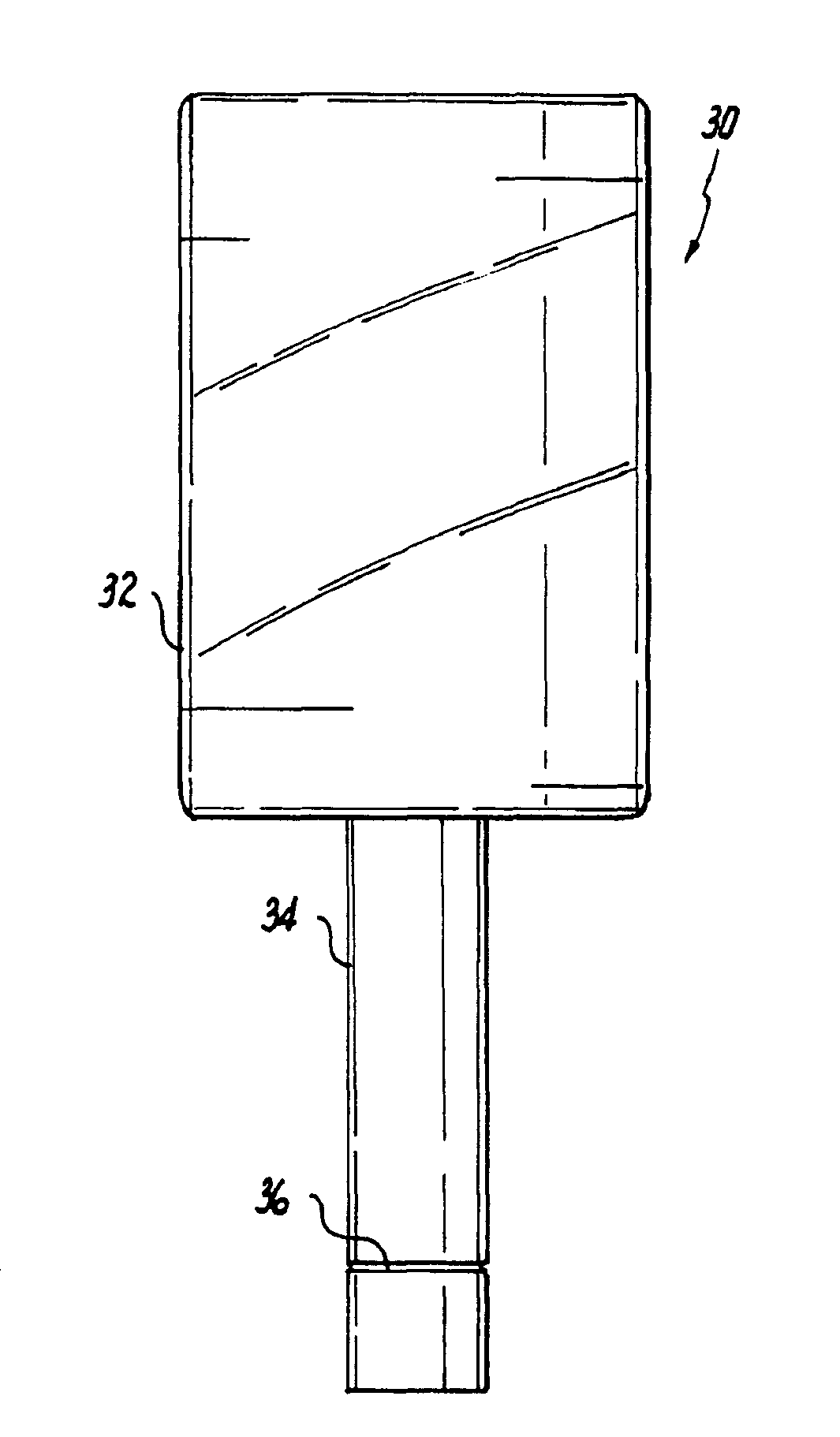
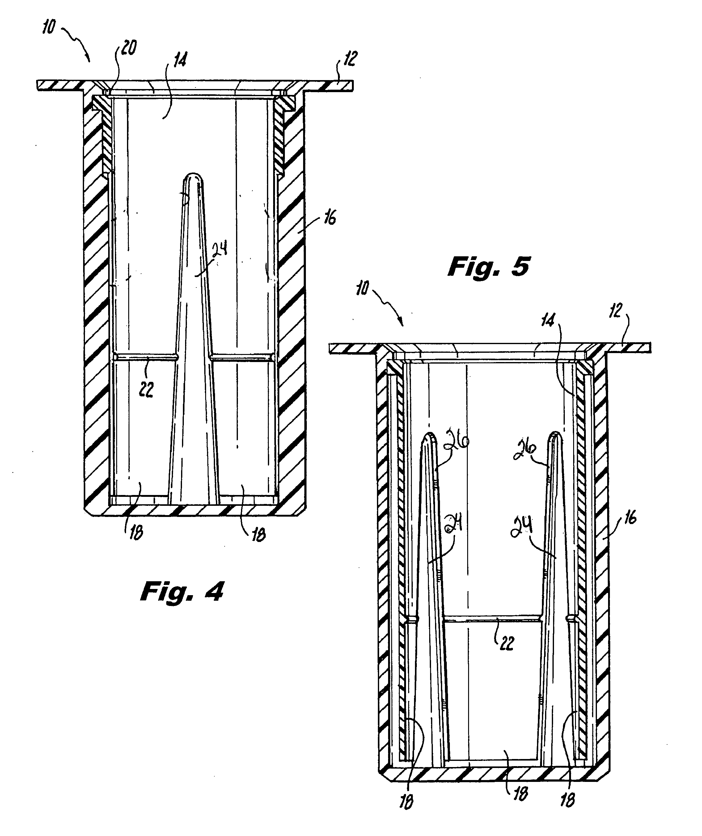
[0061]FIG. 4 shows a cross sectional view through line AA of FIG. 1 which is a cross section through the ribs 26 in the outer mold 16. The film dispenser 10 has a collar 12. The inner mold 14 comprises extensions 18. The inner mold 14 has a collar 20 which allows it to lock within the outer mold 16. The inner mold further comprises ridges 22 which fit into a groove 36 formed in the extended core 30 when the extended core 30 is placed within the film dispenser 10. The inner mold 14 further comprises slots 24 which are located between the extensions 18.

[0062]FIG. 5 shows a cross sectional view of the film dispenser 10 through line BB in FIG. 1 which is a cross section not through the ribs 26 of the outer mold 16....


PUM


Abstract

A film dispenser for dispensing stretch wrap or other flexible materials. The film dispenser is comprised of a separate inner and outer mold. The inner mold is comprised of slots and extensions, and a collar which fits into the outer mold, and inner ridges of said inner mold fit into a groove on an extended core. The outer mold is comprised of ribs which fit into the slots of the inner mold.

Description

FIELD OF THE INVENTION[0001]The present invention relates to a hand dispenser for stretch wrap or other flexible materials.BACKGROUND OF THE INVENTION[0002]U.S. Pat. No. 4,722,493 relates to a holder for dispensing stretch film from a roll comprising a cylindrical body and an arbor rotatably supported on the body. A flexible grip having internal ribs covers the body and the arbor, so that one can by applying finger pressure to the grip brake rotation of the arbor and thus control film tension. The patent teaches that the holder comprises a handle which includes a substantially cylindrical body and a shaft extending from one end of the body. An arbor is journaled on the shaft. Means on the arbor engage the film roll, thereby constraining the roll and the arbor to rotate together on the shaft. A collar is on the arbor adjacent the handle body. One holding the handle body may create a braking torque on the roll by applying radial pressure to the collar.[0003]U.S. Pat. No. 5,203,517 rel...

Claims


Application Information

Patent Timeline
IPC IPC(8): B65H16/02B65H23/06B65D85/672
CPCB65B67/085
Inventor BLOK, JOHANNES
Owner BROADWAY HLDG I
Learn More