Mobile Power System

Inactive Publication Date: 2012-07-19
EVELYN CAPITAL LLC
View PDF23 Cites 14 Cited by
  • Summary
  • Abstract
  • Description
  • Claims
  • Application Information

AI Technical Summary

Benefits of technology

[0024]FIG. 17A and FIG. 17B are a close-up perspective view of the bulkhead wall

Problems solved by technology

While electric power from traditional electrical power grids is readily available in many locations throughout the world, there remain vast regions where no electric power is available.
In addition, other infrastructure, such as paved roads, is likewise lacking and therefore, it is very difficult to even establish a traditional electrical power grid since it can be difficult to access such regions.
Establishing a power transmission network is very costly and requires the development of a complex infrastructure that extends over a substantial number of miles to reach distant end users.
Solar and wind power generation systems are known and can be applied in a number of different applications; however, there are disadvantages associated with each.
For example, these energy sources generally have not been standardized and therefore, they must be custom built for each application and / or at each desired site.
This results in the systems being costly.
In addition, these custom built systems typically require days to assemble and similarly, to disassemble.
Moreover, traditional solar and wind power systems are not modular and typically, once a particular system has been designed, it is very difficult to add components to the system without a costly redesign or modification.
Conventional power transmission systems are neither intended nor are they designed for easy transportation to a desired location.
Also, conventional power generation systems do not provide adequate versatility for receiving power from different types of power generating devices, and for supplying power to a variety of different power receiving devices requiring different types of electrical supply.
As a result, interchanging power receiving devices from the power generating devices is very difficult if not impossible in existing power generating systems.
These existing mobile power systems lack modularity and / or the ability to employ multiple types of power generation devices.
Moreover, these systems do not permit deployment of the power generation devices remotely from the housing in which the system components are transported.
Still further, the transportable design of existing mobile power systems limits their overall total system power output.
For example, in many cases current mobile power systems are limited by their configuration and provide less than 10 kilowatts (kW) of total system power.

Method used


Image

  • Mobile Power System
  • Mobile Power System
  • Mobile Power System

Examples


first embodiment

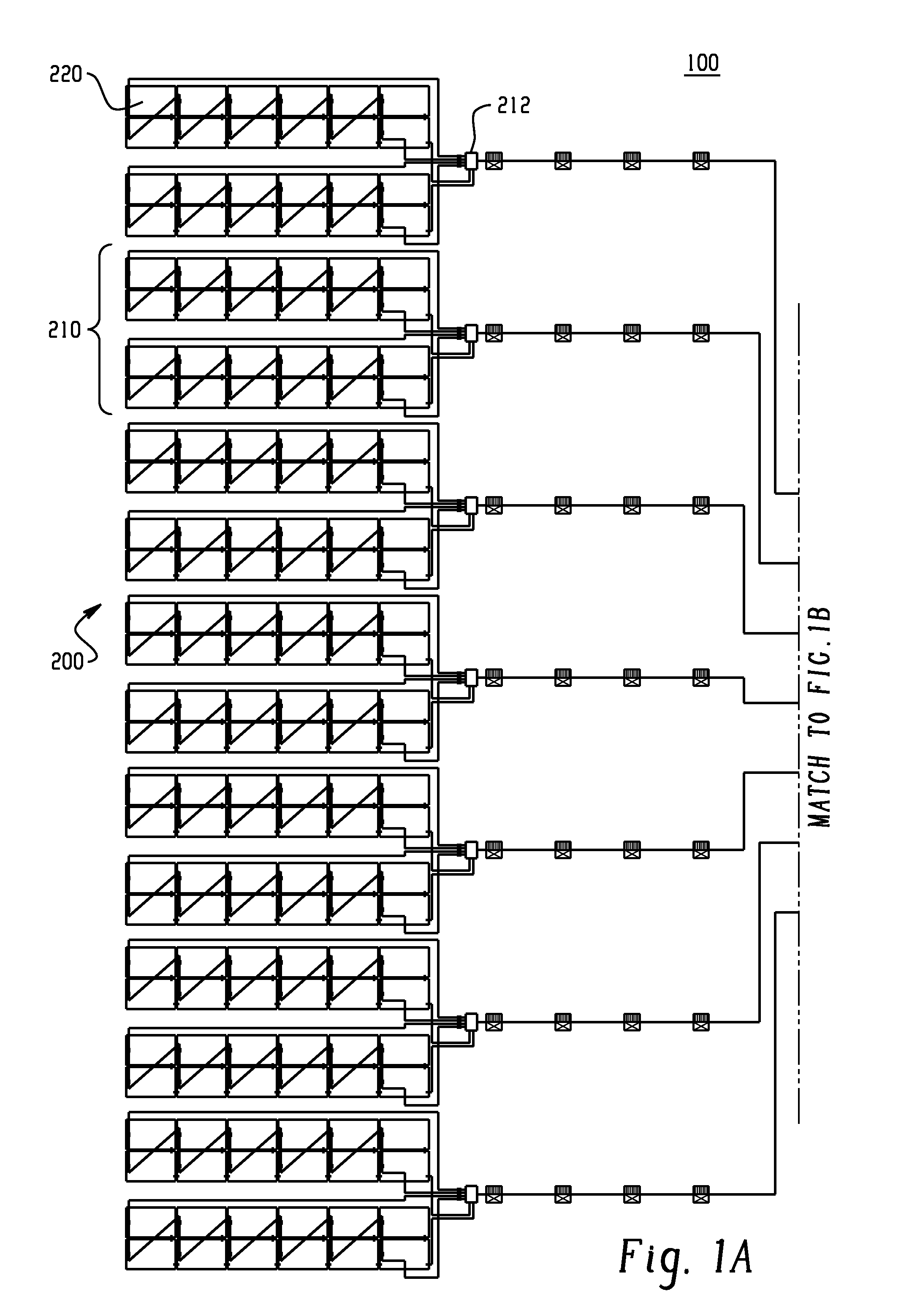
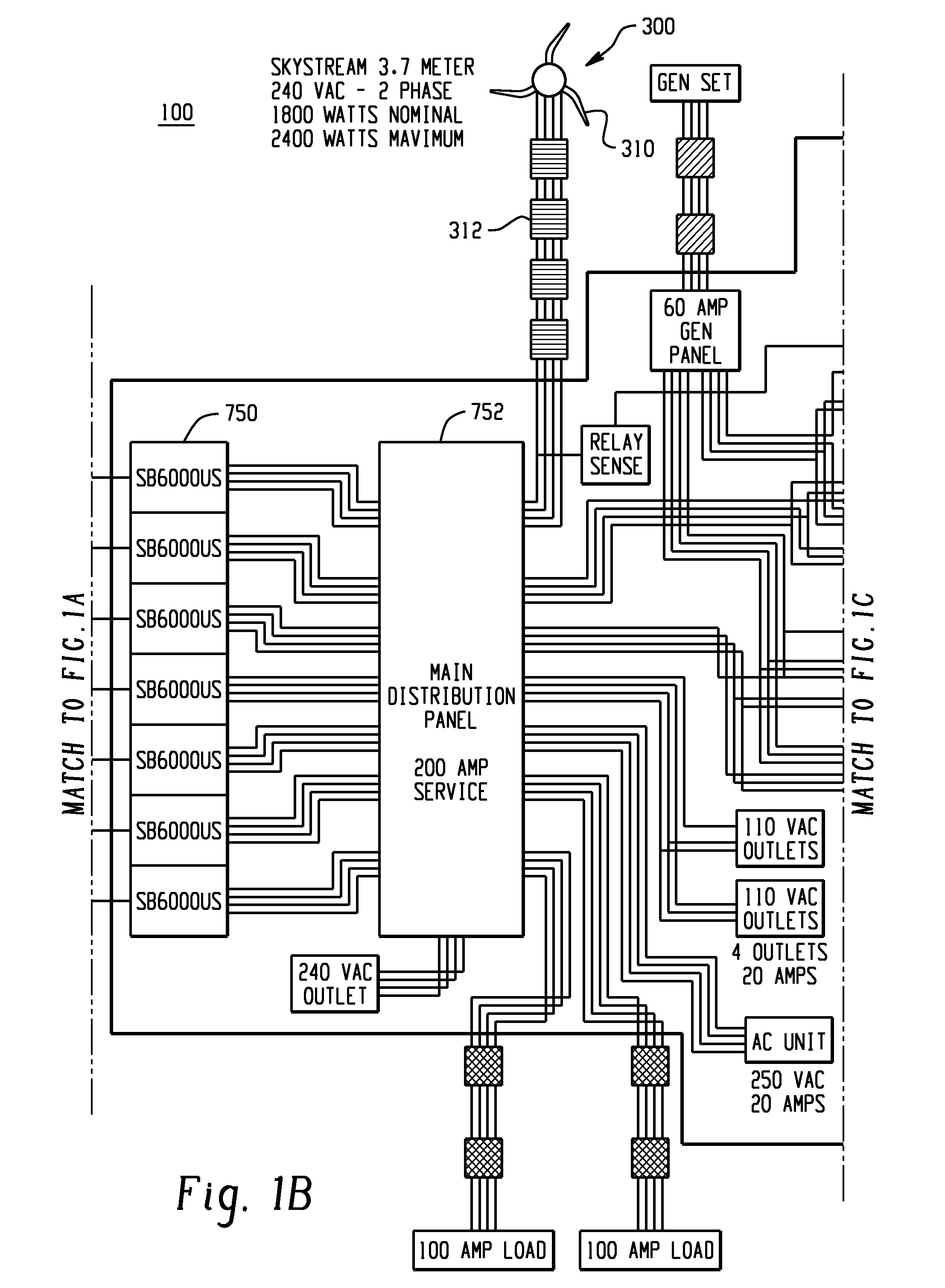
[0029]FIG. 1 is a schematic view of a mobile power system 100 in accordance with the present invention and in a fully deployed, assembled condition. The mobile power system 100 may optionally include communications systems configured to provide monitoring and statistics for the mobile power system 100.

[0030]The mobile power system 100 is generally formed of a number of components. For example, the mobile power system includes a number of power generating devices that are alternative sources of energy that can be harnessed at an in-field location, such as a remote village location. In accordance with one embodiment of the present invention, the mobile power system 100 includes at least a first alternative energy source 200 and a second alternative energy source 300. It will be appreciated that the mobile power system 100 can include more than two alternative energy sources. In the illustrated embodiment, the first alternative energy source 200 is a solar based energy source and the s...

second embodiment

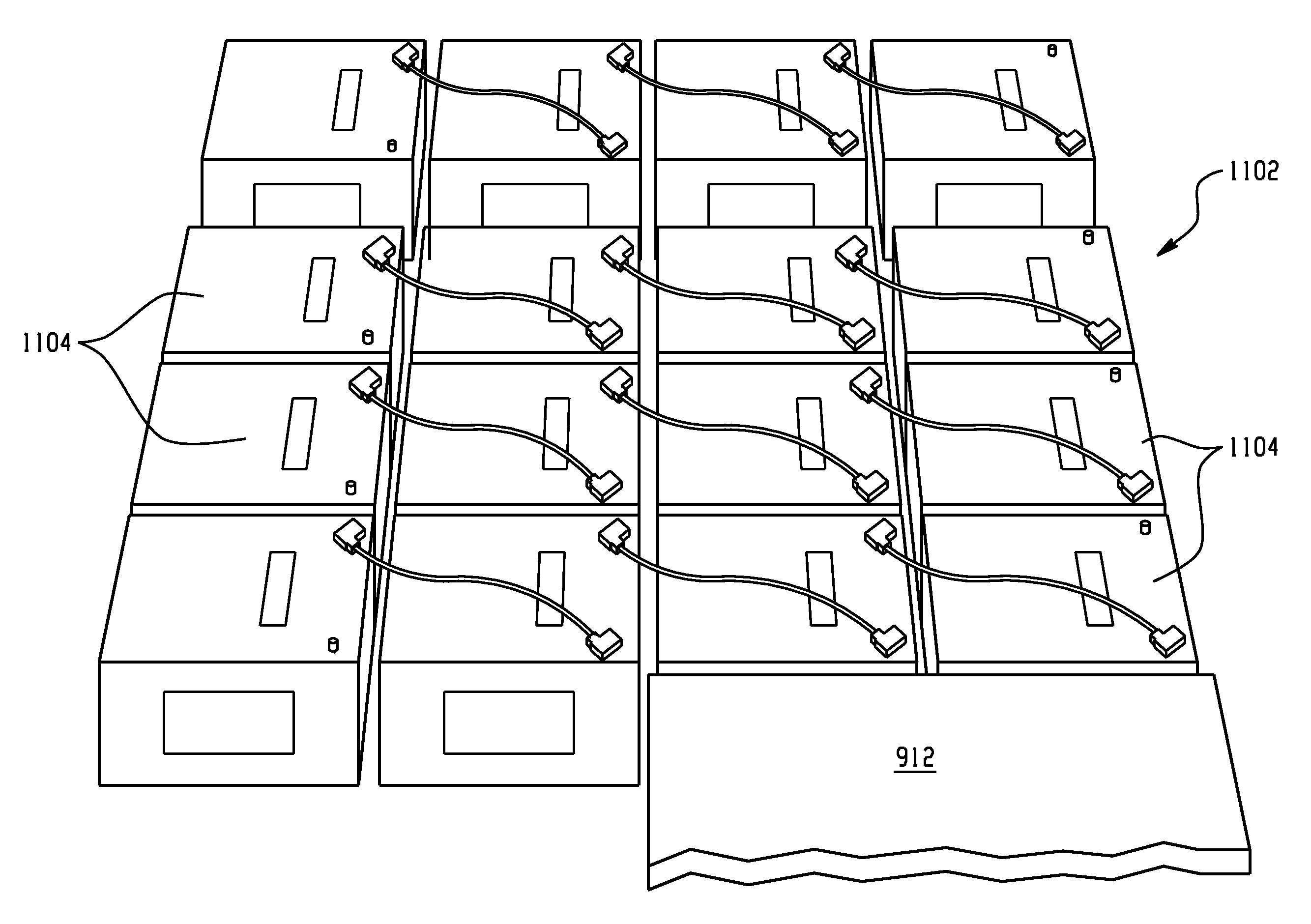
[0077]Referring now to FIG. 20, a schematic view of a mobile power system 2100 in accordance with the present invention and in a fully deployed, assembled condition is shown. The mobile power system 2100 may optionally include communications systems configured to provide monitoring and statistics for the mobile power system 2100.

[0078]The mobile power system 2100 is generally formed of a number of components. For example, the mobile power system includes a number of power generating devices that are alternative sources of energy that can be harnessed at an in-field location, such as a remote village location. In accordance with one embodiment of the present invention, the mobile power system 2100 includes one or more alternative energy sources 2200. In the illustrated embodiment, the alternative energy source 2200 is a solar based energy source.

[0079]FIG. 20 further illustrates a top-down schematic view of an exemplary solar panel array 2210 of the solar powered generating device 22...


PUM


Abstract

A mobile power system includes a plurality of energy sources including a solar powered generating source and a plurality of electronic and telecommunications components configured to receive the power generated by the plurality of energy sources and convert the power generated to direct current power. The system also includes a plurality of batteries configured to store the direct current power and a main distribution panel including one or more short circuit ground fault protection devices configured to isolate a short circuit ground fault in less than approximately two hundred milliseconds. The system also includes one or more transportable housings configured to hold the plurality of energy sources, the plurality of electronic and telecommunications, the main distribution panel and the plurality of batteries during transport of the housing.

Description

CROSS REFERENCE TO RELATED APPLICATIONS[0001]This application is a continuation-in-part of U.S. application Ser. No. 12 / 878,765 filed Sep. 9, 2010, which claims the benefit of U.S. Provisional Application. Ser. No. 61 / 240,963; filed Sep. 9, 2009; U.S. Provisional Patent Application No. 61 / 265,632; filed Dec. 1, 2009; U.S. Provisional Patent Application Ser. No. 61 / 265,629; filed Dec. 1, 2009; and U.S. Provisional Patent Application Ser. No. 61 / 310,121; filed on Mar. 3, 2010; all of which are incorporated herein by reference in their entirety.BACKGROUND OF THE INVENTION[0002]The present invention relates to power systems and more particularly, to mobile, self-contained power systems that can be easily constructed in an in-field environment. The self-contained power systems may include communications systems configured to provide monitoring and statistics for the self-contained power systems.[0003]Electric power is typically routed from power generating stations along an electrical po...

Claims


Application Information

Patent Timeline
IPC IPC(8): H02B1/26
CPCF03D9/007H02J7/35Y02E10/72Y02E10/766Y02E10/763H02J3/386H02J3/387Y02E10/563Y02E10/566H02J3/383H02J2300/40H02J2300/10H02J2300/30H02J2300/28H02J2300/24H02J3/381Y02E10/56Y02E10/76
Inventor PRAX, ELDONWALDROP, STANNICELY, JEFF
Owner EVELYN CAPITAL LLC
Why Eureka
Try Eureka