Apparatus and Method to Apply Liquid to Solid Waste Disposal Site

a technology of liquid application and solid waste, applied in the direction of soil-shifting machines/dredgers, transportation and packaging, nuclear engineering, etc., can solve the problems of generating “leachate”, adding cost to landfill operations, and prior art techniques for leachate disposal on the working face are generally confined

Inactive Publication Date: 2012-07-19
S & D TECH
View PDF12 Cites 2 Cited by
  • Summary
  • Abstract
  • Description
  • Claims
  • Application Information

AI Technical Summary

Problems solved by technology

One of the side effects of this disposal and compacting process is the generation of “leachate”.
This is an added expense to landfill operations.
Landfill leachate is very high in organics, nitrogen, metals and other toxic materials, and is a significant environmental and health concern if released into the environment untreated.
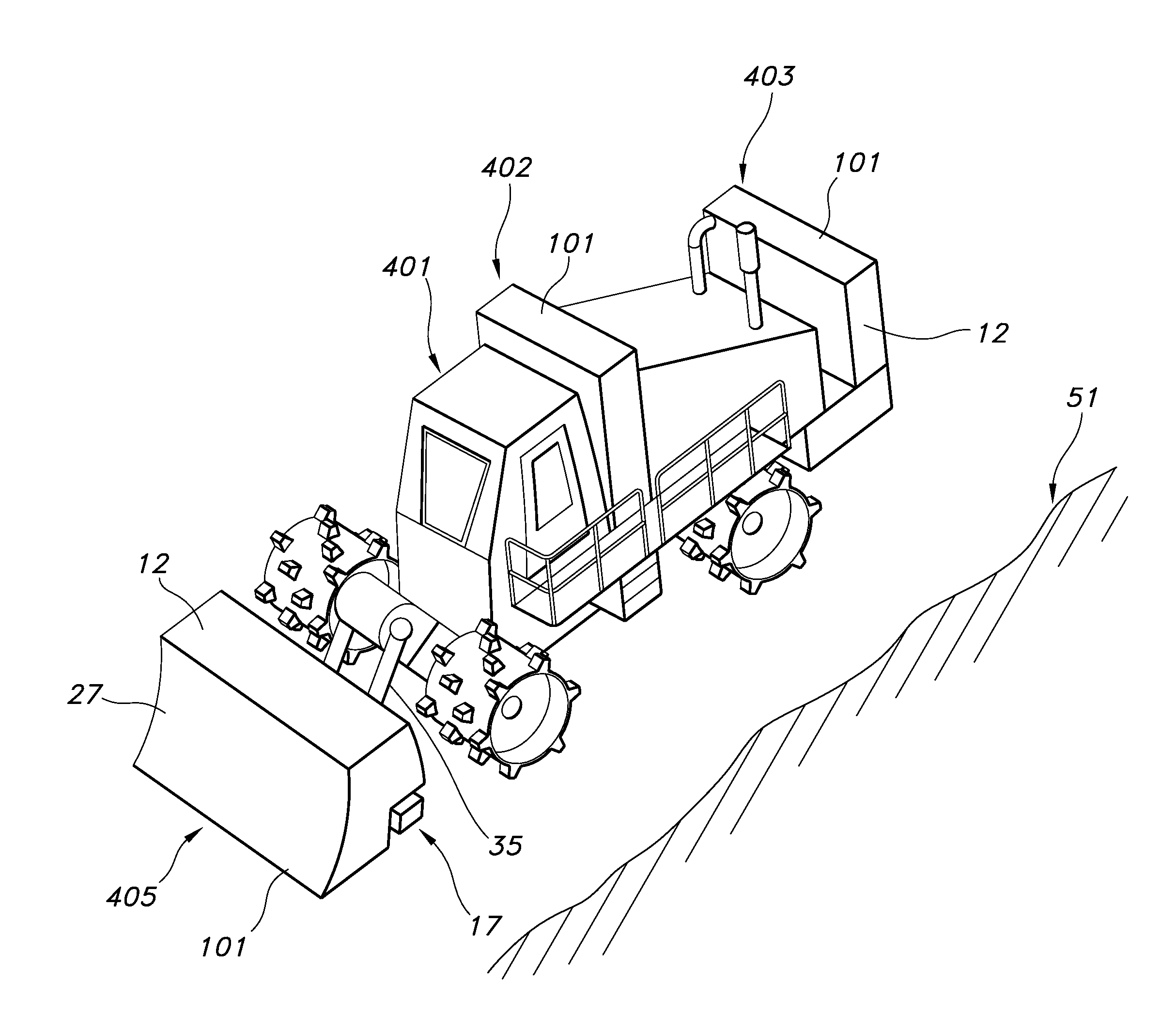
Prior art techniques for leachate disposal on the working face have generally been confined to the use of a stray nozzles and portable pumps.
Further this mist could cause potential health hazard to personnel working nearby.
This will cause an uneven distribution of the leachate over the working face waste.
This would obviously make the compaction uneven and sporadic.

Method used


Image

  • Apparatus and Method to Apply Liquid to Solid Waste Disposal Site
  • Apparatus and Method to Apply Liquid to Solid Waste Disposal Site
  • Apparatus and Method to Apply Liquid to Solid Waste Disposal Site

Examples


Embodiment Construction

[0019]The present invention may be understood more readily by reference to the following detailed description of the invention. It is to be understood that this invention is not limited to the specific devices, methods, conditions or parameters described herein, and that the terminology used herein is for the purpose of describing particular embodiments by way of example only and is not intended to be limiting of the claimed invention. Also, as used in the specification including the appended claims, the singular forms “a,”“an,” and “the” include the plural, and reference to a particular numerical value includes at least that particular value, unless the context clearly dictates otherwise. Ranges may be expressed herein as from “about” or “approximately” one particular value and / or to “about” or “approximately” another particular value. When such a range is expressed, another embodiment includes from the one particular value and / or to the other particular value. Similarly, when valu...


PUM


Abstract

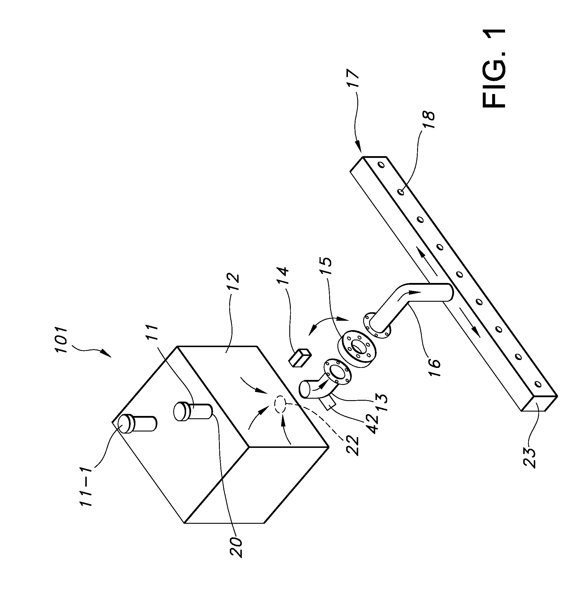
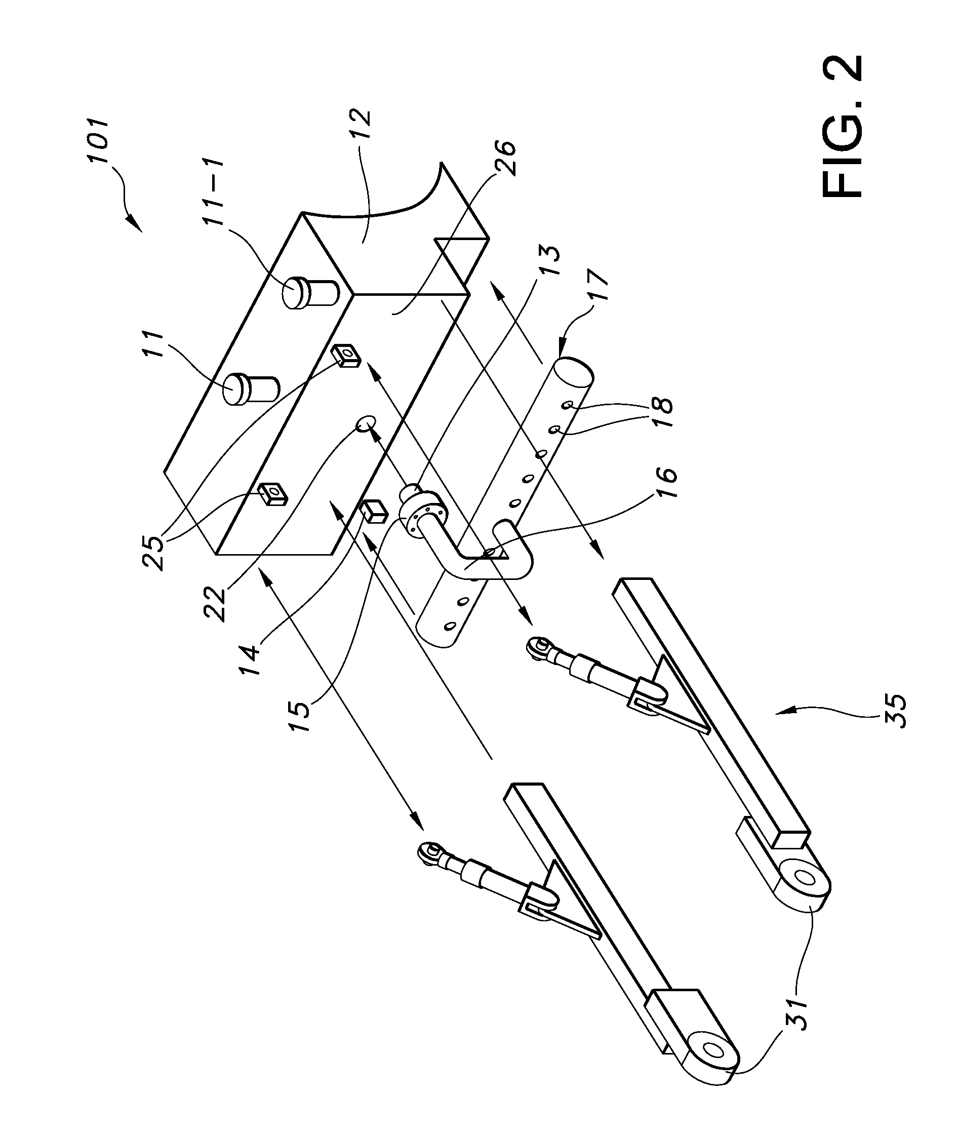
This invention relates to a method to apply waste treatment liquid to a solid waste disposal site by filing a storage tank with waste treatment liquid, connecting the liquid storage tank with a vehicle for solid waste compacting and releasing the waste treatment liquid to a portion of solid waste site in need of moisture. This invention further provided an apparatus for distributing waste treatment liquid over the working face of a solid waste disposal site includes an inflow conduit, a storage tank, an outflow conduit, a control valve that contains a remote-valve control; manifold inlet conduit attached to the control valve, and a manifold to allow the liquid received from the manifold inlet conduit to be distributed evenly over the working face.

Description

CROSS REFERENCE TO RELATED APPLICATIONS[0001]This application claims the benefit of U.S. Provisional Application Ser. No. 61 / 461,262 filed Jan. 15, 2011 under 35 U.S.C. Section 1.119(e) hereby specifically incorporated by reference in its entirety.FIELD OF THE INVENTION[0002]This invention relates to apparatus and method to distribute liquid to solid waste disposal site for compacting and collecting solid waste.BACKGROUND OF THE INVENTION[0003]In the solid waste industry typically permitted active landfills are used for the disposal of solid waste. The portion of the landfill where waste is actually being unloaded, placed and compacted is call the “working face” of the land fill. This working face is where waste is placed and compacted by vehicles. Generally these vehicles are track or cleated / chopper wheel driven. These vehicles not only position the waste for efficient air space utilization of land fill capacity, but most importantly compact the waste for maximum utilization of th...

Claims


Application Information

Patent Timeline
Patent Type & Authority Applications(United States)
IPC IPC(8): B09B3/00B09B5/00
CPCB09B3/0016B09B1/00E02F3/815E02F3/961E02F3/962B09B3/80
Inventor KEYLOR, STEVEN LEESHIRLEY, LINDSEY
Owner S & D TECH
Why Eureka
Try Eureka