Heat Transfer Pad Having Localized Treatment Zones

a heat transfer pad and treatment zone technology, applied in the field of therapeutic treatment, can solve the problems of periodic treatment temperature fluctuations, high manufacturing and maintenance costs, and material warming at low temperatur

Active Publication Date: 2012-07-19
BREG
View PDF9 Cites 22 Cited by
  • Summary
  • Abstract
  • Description
  • Claims
  • Application Information

AI Technical Summary

Benefits of technology

[0007]Each flow channel has a defined continuous containment width along its length which substantially prevents fluid communication between the first and second flow channels, thereby substantially preventing mixing of the first flow stream while in the first flow channel with the second flow stream while in the second flow channel. The defined continuous containment width of the first flow channel preferably substantially prevents back mixing of the first flow stream with itself within the first flow channel and the defined continuous containment width of the second flow channel likewise preferably substantially prevents back mixing of the second flow stream with itself within the second flow channel.
[0011]The present invention is alternately characterized as a heat transfer pad including a pad inlet port for feeding a heat transfer fluid to the pad, a pad outlet port for discharging the heat transfer fluid from the pad and a bladder having an internal flowpath for the heat transfer fluid to flow therethrough. The internal flowpath extends from the pad inlet port to the pad outlet port and is divided into a first flow channel and a second flow channel, both of which are between the pad inlet and outlet ports. A first flow stream of the heat transfer fluid flows through the first channel at a first flow rate and a second flow stream of the heat transfer fluid flows through the second flow channel at a second flow rate. In accordance with one embodiment, each flow channel has a defined continuous containment width along its length which substantially prevents fluid communication between the first and second flow channels, thereby substantially preventing mixing of the first flow stream while in the first flow channel with the second flow stream while in the second flow channel.
[0013]The present invention is alternately characterized as a heat transfer pad including a pad inlet port for feeding a heat transfer fluid to the pad, a pad outlet port for discharging the heat transfer fluid from the pad and a bladder having an internal flowpath for the heat transfer fluid to flow therethrough. The internal flowpath extends from the pad inlet port to the pad outlet port and is divided into a first flow channel and a second flow channel, both of which are between the pad inlet and outlet ports. A first flow stream of the heat transfer fluid flows through the first channel at a first flow rate and a second flow stream of the heat transfer fluid flows through the second flow channel at a second flow rate. Each flow channel has a defined continuous containment width along its length which substantially prevents fluid communication between the first and second flow channels, thereby substantially preventing mixing of the first flow stream while in the first flow channel with the second flow stream while in the second flow channel.

Problems solved by technology

One disadvantage of such devices is that the low temperature materials become warmer as they remain in contact with the body and the body transfers heat to the low temperature materials.
However, constant replenishment of these materials is cumbersome and inconvenient, and results in periodic treatment temperature fluctuations.
These fluid circulation systems in general are relatively complex, rendering them costly to manufacture and maintain, as well as difficult to operate.
Accordingly, the systems are not practical for widespread use.

Method used


Image

  • Heat Transfer Pad Having Localized Treatment Zones
  • Heat Transfer Pad Having Localized Treatment Zones
  • Heat Transfer Pad Having Localized Treatment Zones

Examples


Embodiment Construction

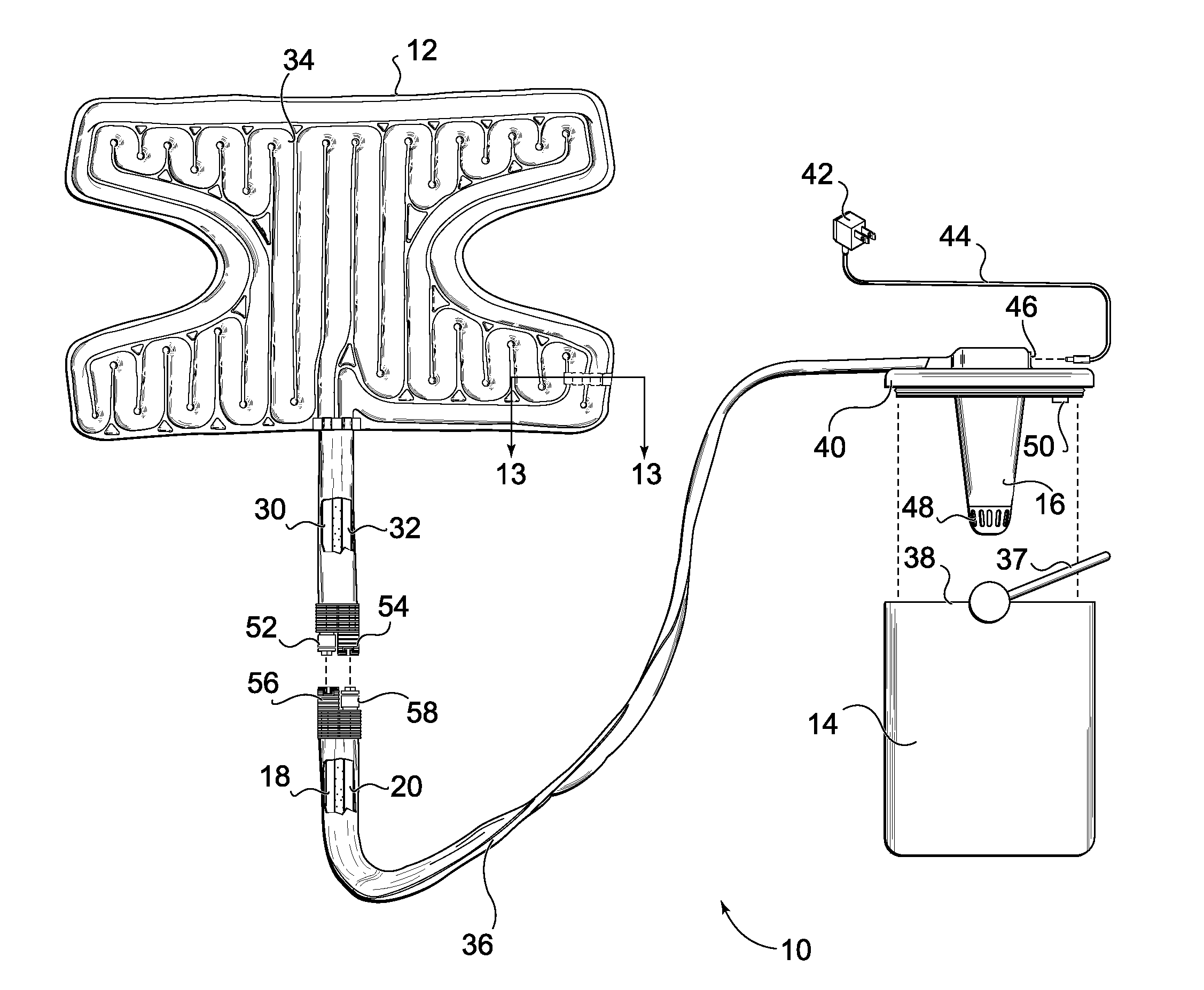
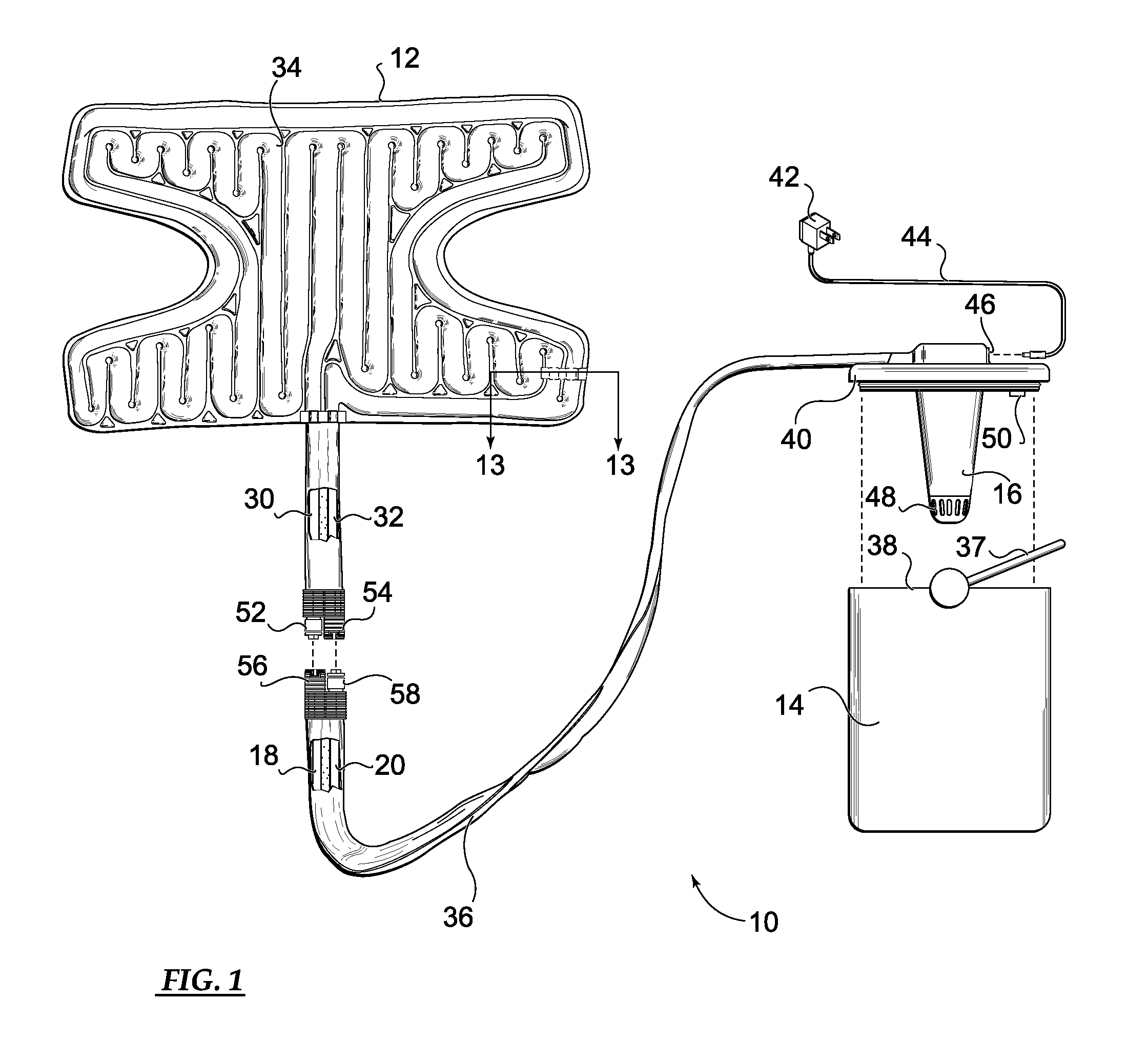
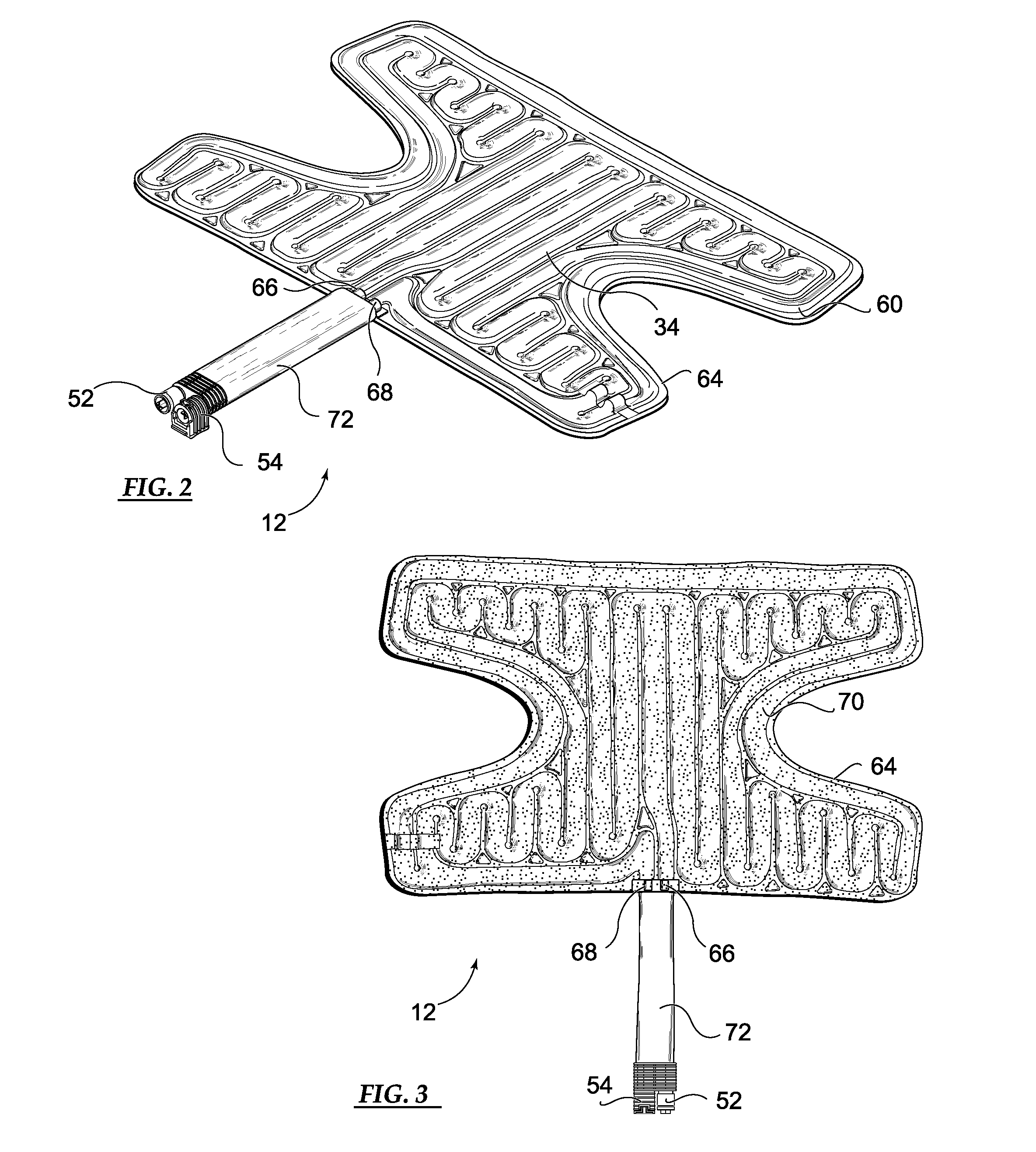
[0033]FIG. 1 shows an exemplary non-ambient temperature therapy system generally designated 10 in which a heat transfer pad of the present invention has utility. The system 10 comprises the heat transfer pad 12, through which a heat transfer fluid is circulated, and a reservoir 14, which is a source of fresh heat transfer fluid. The system further comprises a pump 16, a fresh fluid feed line 18 and a spent fluid return line 20 (shown in a partial cutaway) which enable continuous steady-state circulation of the heat transfer fluid from the reservoir 14, through the pad 12 and back to the reservoir 14 in a manner described in detail below.

[0034]The intended use of the system 10 is for administering non-ambient temperature therapy to a patient on whom the heat transfer pad 12 is mounted. Although the patient may use the system 10 to self-administer the therapy during individual sessions, the overall non-ambient temperature therapy program is typically under the direction of a health ca...


PUM


Abstract

A heat transfer pad includes a pad inlet port for feeding a heat transfer fluid to the pad, a pad outlet port for discharging the heat transfer fluid from the pad and a bladder having an internal flowpath for the heat transfer fluid which extends from the pad inlet port to the pad outlet port. The internal flowpath is divided into a first flow channel and a second flow channel through which first and second flow streams of the heat transfer fluid, respectively, flow between the pad inlet and outlet ports. A first flow restrictor is positioned downstream in the first flow channel and a second flow restrictor is correspondingly positioned downstream in the second flow channel and the flow restrictors are configured to create substantial back pressures in the first and second flow channels, respectively.

Description

TECHNICAL FIELD[0001]The present invention relates generally to therapeutic treatment of bodily injuries and ailments by cooling or heating an affected region of the body of a patient, and more particularly, to a heat transfer pad having a non-ambient temperature heat transfer fluid circulated therethrough which is positioned on the affected region to cool or heat the region.BACKGROUND OF THE INVENTION[0002]Bodily injuries and ailments are commonly treated by applying a non-ambient temperature material to the affected region of the body. For example, a low temperature material, typically applied in the form of cold water, ice or a cold pack, may advantageously inhibit swelling in the region of the injury. A high temperature material, typically applied in the form of hot water, a hot pack or an active heating element, may advantageously reduce pain and promote healing. A number of splint devices are known in the art for applying non-ambient temperature materials to injured or otherwi...

Claims


Application Information

Patent Timeline
Patent Type & Authority Applications(United States)
IPC IPC(8): A61F7/08
CPCF28F3/12A61F2007/0228A61F2007/0054A61F7/02A61F7/00A61F2007/004
Inventor JOHNSON, MICHAEL G.MAH, STEFANIE L.FOUT, JAMES M.HANSEN, CHRISTIAN L.
Owner BREG
Why Eureka
Try Eureka