
Method for estimating the direction of a moving solid

Inactive Publication Date: 2012-07-19
MOVEA +1
View PDF21 Cites 177 Cited by
  • Summary
  • Abstract
  • Description
  • Claims
  • Application Information

AI Technical Summary

Benefits of technology

[0016]Measuring, at a reference instant n0 for which the solid is devoid of inherent acceleration, gravitational field and magnetic field vectors in a reference frame of the solid, said measured vectors making it possible to determine an orientation of said solid in the inertial reference frame at the reference instant n0;
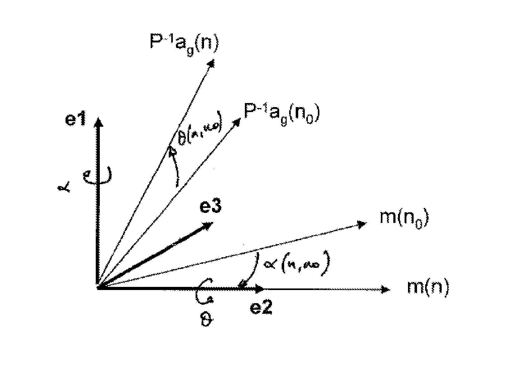
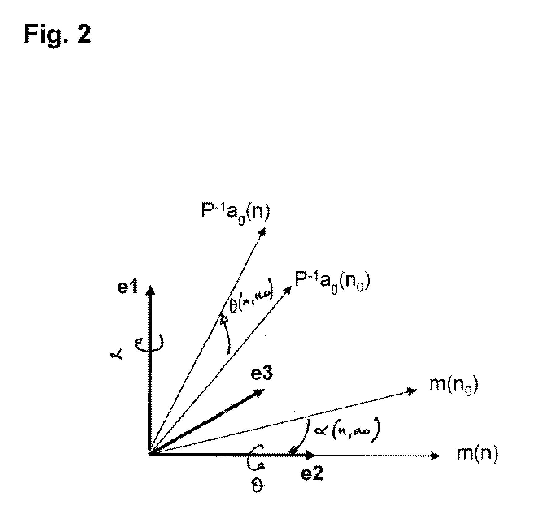
[0018]Estimating a matrix U(n,n0) making it possible to ensure the rotation of said orientation of the solid, previously determined at the reference instant n0, to an orientation at a subsequent instant n,
[0033]Measuring, at a reference instant n0 for which the solid is devoid of inherent acceleration, gravitational field and magnetic field vectors in a reference frame of the solid, said measured vectors making it possible to determine an orientation of said solid in the inertial reference frame at the reference instant n0;
[0035]Estimating a matrix U(n,n0) making it possible to ensure the rotation of said orientation of the solid, previously determined at the reference instant n0, to an orientation at a subsequent instant n,

Problems solved by technology

However, it is not generally possible to distinguish, under dynamic conditions, the contribution of the gravitational field component from that of the inherent acceleration in the acceleration vector measured by the accelerometer.
However, the processing of the signal becomes particularly complex because signals from a plurality of sensors (accelerometers, gyrometers, magnetometers, etc.) have to be combined, the measurements from each sensor have specific uncertainties and some of them (for example, the gyrometers) have a temporal drift.
However, the uncertainty in the extrapolated gravitational field vector is all the more significant because it impacts the three spatial components of said vector.
The calculated Euler angles are therefore significantly inaccurate.

Method used


Image

  • Method for estimating the direction of a moving solid
  • Method for estimating the direction of a moving solid
  • Method for estimating the direction of a moving solid

Examples


Embodiment Construction

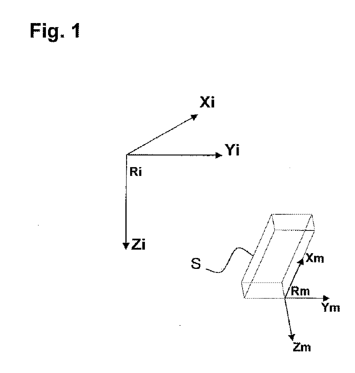
[0048]A solid S in motion in an inertial fixed reference frame Ri represented in FIG. 1 is considered. The inertial fixed reference frame Ri is defined by axes Xi, Yi, Zi directed respectively toward the local magnetic North, toward the local magnetic East and toward the ground. In this reference frame, also called NED (the acronym standing for North-East-Down), the terrestrial gravitational field and the terrestrial magnetic field may be written:

g=g(001)andmT=mT(cosκ0sinκ)

where the angle of inclination κ is about 60° in France.

[0049]The solid is equipped with an accelerometer and a magnetometer, both mounted solidly on said solid. Said accelerometer and said magnetometer each comprise three sensitivity axes, which, preferably, coincident and form a mobile reference frame Rm=(Xm,Ym,Zm) of the solid.

[0050]In the case where the axes of the accelerometer do not coincide with those of the magnetometer, it is assumed that at each instant an operation of conversion from the reference fram...


PUM


Abstract

The invention relates to a method for estimating the orientation in an inertial reference frame of a solid in motion equipped with an accelerometer and a magnetometer which are mounted on said solid.According to this method, an orientation of the solid is measured at a reference instant, said orientation being defined by a rotation matrix for rotating from the mobile reference frame of the solid at the reference instant to the inertial reference frame. A rotation matrix for rotating between the orientation of the solid at a subsequent instant n and said orientation of the solid at the reference instant is thereafter estimated. The orientation of the solid at the instant n is thereafter determined with the aid of the previously estimated rotation matrix and of the known orientation of the solid at the reference instant.

Description

CROSS-REFERENCE TO RELATED APPLICATIONS[0001]This application is a national phase application under 35 U.S.C §371 of PCT / EP2010 / 060802, filed Jul. 26, 2010, which claims priority to French Patent Application No. 0955435, filed Jul. 31, 2009, the entire contents of which are expressly incorporated herein by reference.BACKGROUND[0002]1. Field of the Invention[0003]The present invention pertains to the general field of estimation of the orientation and motion of a solid.[0004]It relates to a method for estimating the orientation in an inertial reference frame of a solid in motion. It also pertains to a method for estimating the inherent acceleration of said solid.[0005]2. Description of the Related Art[0006]In a certain number of fields, it may be essential to determine the orientation and the motion of a solid in motion. Such is the case, for example, in robotics, teleoperations, and device calibrations, but also in the fields of multimedia and video games, as well as in the biomechan...

Claims


Application Information

Patent Timeline
IPC IPC(8): G06F15/00
CPCG01C21/16
Inventor JALLON, PIERREBONNET, STEPHANE
Owner MOVEA
Learn More