Optical Pumping Magnetometer

a magnetometer and optical technology, applied in the field of magnetometers, can solve the problems of inability to efficiently excite the alkali metal gas in the glass cell, easy polarization of optical paths, uneven temperature of optical fibers, etc., and achieve the effect of preventing collapse of polarization or fluctuation and stable operation of optical paths

Active Publication Date: 2013-10-10
HITACHI LTD
View PDF5 Cites 100 Cited by
  • Summary
  • Abstract
  • Description
  • Claims
  • Application Information

AI Technical Summary

Benefits of technology

[0012]The present provides an optical pumping magnetometer in which the optical axis of a laser beam introduced into a glass cell of a magnetic sensor is stable and is easily controllable, and the factor of the collapse of polarization of the laser beam is eliminated and mixture of magnetic noise is eliminated, so as to realize a stable operation.
[0017]According to an aspect of the present invention, it is possible to realize a stable operation of an optical pumping magnetic sensor with a structure having a glass-cell heat preserving mechanism to prevent collapse of polarization or fluctuation of light intensity of a laser beam incident on the glass cell so as not to cause influence on the laser beam.

Problems solved by technology

Accordingly, in some cases it is difficult to adjust the laser beam optical path, or even when the optical path is controlled, the optical path is easily shifted since the length of the optical path is long, and re-control is required.
However, when the glass cell is maintained at a temperature higher than a room temperature and the density of alkali metal gas in the glass cell is increased, the structure where the glass cell is included in the optical fiber has temperature unevenness in the optical fiber by maintaining the temperature of the glass cell.
When the status of the laser beam is changed, it is impossible to efficiently excite the alkali metal gas in the glass cell.
However, noise occurs when the laser beam is swayed due to the influence of air flow by the heated air and the magnetic measurement signal is fluctuated.

Method used


Image

  • Optical Pumping Magnetometer
  • Optical Pumping Magnetometer
  • Optical Pumping Magnetometer

Examples


first embodiment

]

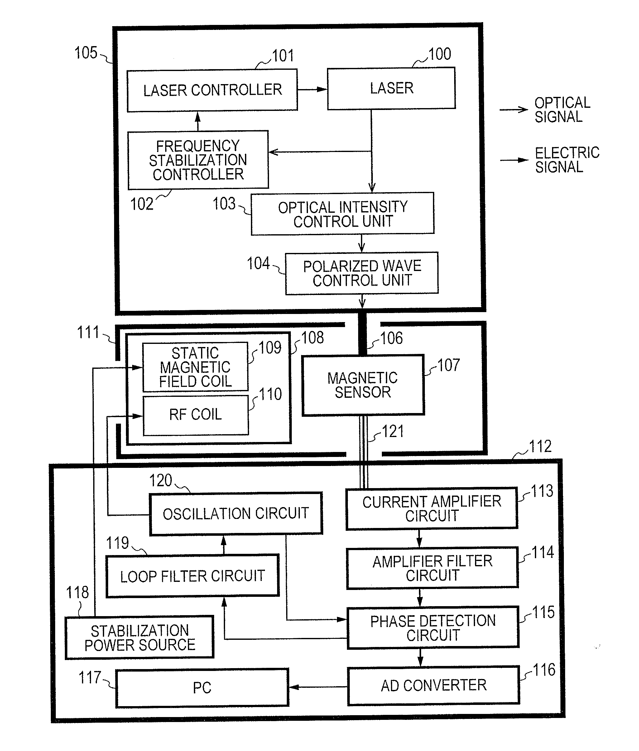
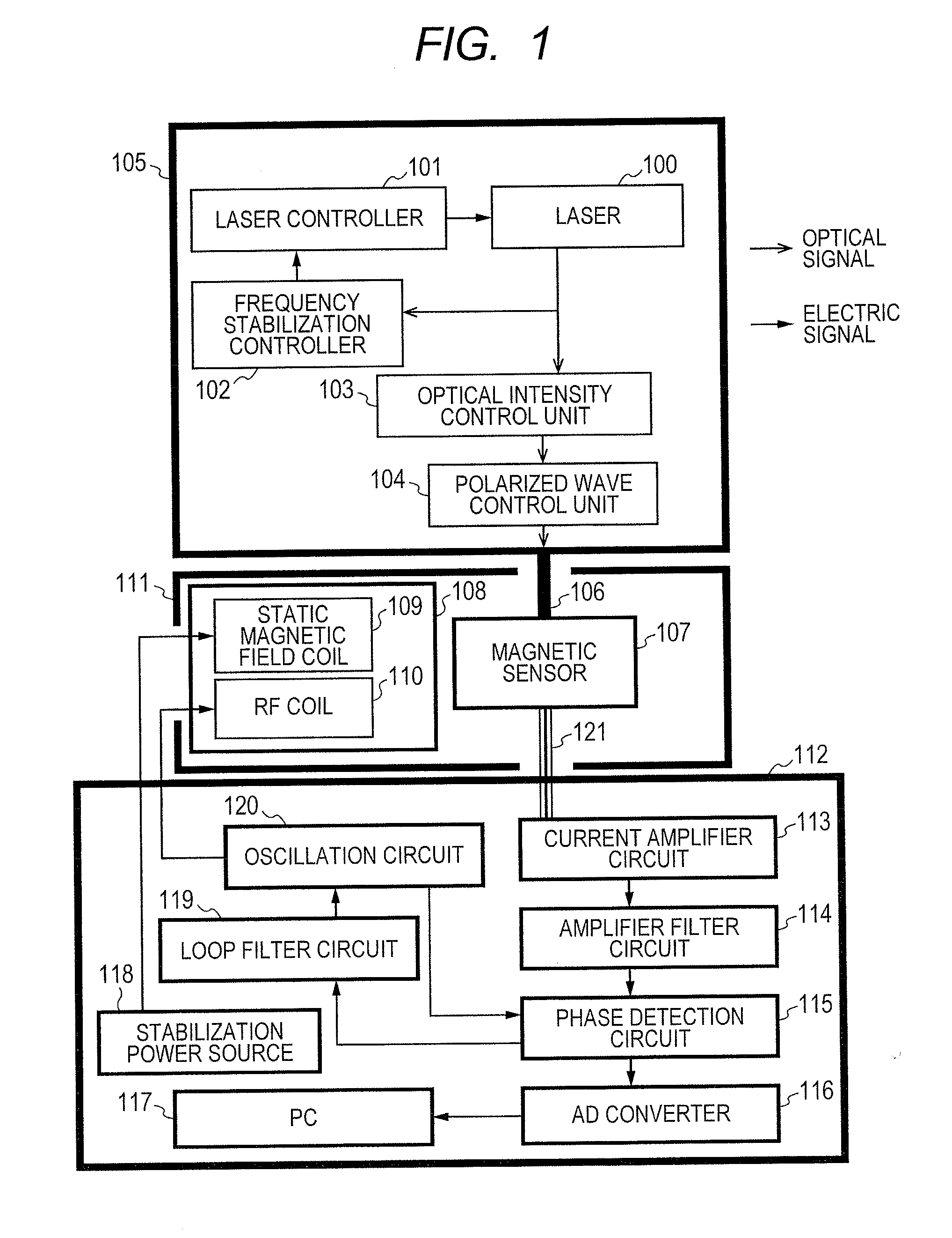
[0028]FIG. 1 schematically shows the configuration of a magnetometer according to a first embodiment of the present invention. The magnetometer has a light source 105, a coil 108, a magnetic sensor 107, and a signal control processor 112.

[0029]As the light source, a lamp may be used, however, it is preferable to use a stable and high-performance laser. Accordingly, a laser 100 is used in the light source 105 according to the present embodiment.

[0030]It is necessary for the laser to operate the optical pumping magnetic sensor to satisfy the following conditions. It is necessary to perform oscillation around a frequency of excitation transition (line D1 and line D2) of alkali metal entered the glass cell in the magnetic sensor. It is necessary to perform single mode laser oscillation at a stable oscillation frequency. The laser beam width must be equal to or less than a natural width of alkali metal atoms. It is necessary to output a laser beam to sufficiently excite the alkali metal...

second embodiment

]

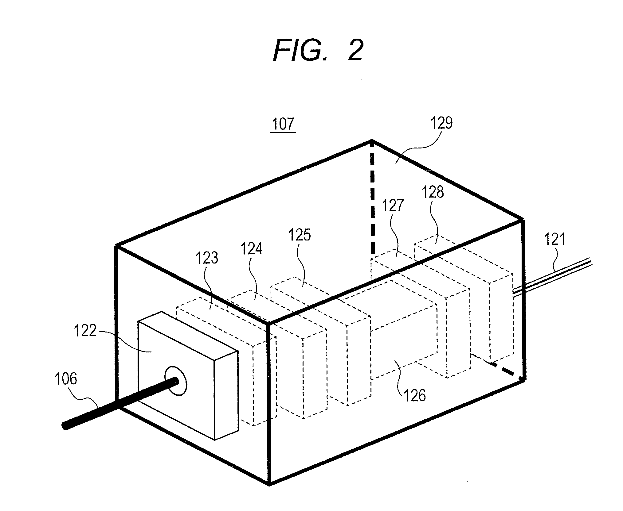
[0041]In a second embodiment of the present invention, the configuration of the magnetic sensor is different from that in the above-described first embodiment. FIG. 3 shows the structure of the magnetic sensor 131 according to the second embodiment. In comparison with the magnetic sensor 107 according to the first embodiment as shown in FIG. 2, the difference is that the photodetector 128 is omitted, and the laser beam passed through the magnetic-sensor glass cell 126 is collected with the light collecting lens 127 at an end surface of the multi-mode optical fiber 130 and outputted with the multi-mode optical fiber 130 to the outside the magnetic sensor 131. The multi-mode optical fiber 130 is attached to the non-magnetic case 129 with a non-magnetic fiber connector 152. The structure from the polarized wave holding optical fiber 106 to introduce the excitation light to the glass cell 126 is the same as that of the magnetic sensor 107 according to the first embodiment in FIG. 2.

[00...

third embodiment

[0045]In a third embodiment of the present invention, the magnetic sensor 107 according to the first embodiment has a heat preserving mechanism heat preserving mechanism. FIG. 5 shows the structure of a magnetic sensor 134 in the magnetometer according to the third embodiment. In comparison with the magnetic sensor 107 according to the first embodiment shown in FIG. 2, the difference is that chambers 138 and 139 which warm water flows in are provided in an outer surface of a glass wall of the magnetic-sensor glass cell 126. The magnetic-sensor non-magnetic case 129 is provided with a warm water inflow port 135 connected to the chamber 138. The chamber 138 is connected to the chamber 139 via a connection unit 137, and further, the chamber 139 is connected to a warm water outflow port 136 so as to pass warm water through. The structure from the polarized wave holding optical fiber 106 to introduce the excitation light to the magnetic-sensor photodetector 128 to detect the laser beam p...


PUM


Abstract

Stable magnetic field measurement is enabled without collapse of polarization or fluctuation of intensity of a laser beam incident on a glass cell of an optical pumping magnetic sensor. Excitation light generated with a light source, having optimized light intensity and polarized wave, through frequency stabilization, intensity control and polarized-wave control, is introduced via a polarized wave holding optical fiber to a magnetic sensor provided in a magnetic shield, and magnetic field measurement is performed by optical pumping using magneto-optical properties of spin-polarized alkali metal. The magnetic sensor has a structure where a lens, a polarization optical device, the glass cell and a photodetector, are integrally accommodated in a non-magnetic case.

Description

CLAIM OF PRIORITY[0001]The present application claims priority from Japanese patent application JP 2012-086954 filed on Apr. 6, 2012, the content of which is hereby incorporated by reference into this application.BACKGROUND OF THE INVENTION[0002]1. Field of the Invention[0003]The present invention relates to a magnetometric technique utilizing magneto-optical effects by optical pumping.[0004]2. Description of the Related Art[0005]An optical pumping magnetometer utilizing magneto-optical effects by optical pumping uses a glass cell filled with alkali metal gas (e.g., potassium, rubidium or cesium) as a sensor. A static magnetic field is applied to the glass cell, to Zeeman-split energy level of the alkali metal in the glass cell. Then the glass cell is irradiated with the polarized-status-operated light such as linear polarized light, circularly polarized light or elliptically polarized light, or intensity / phase-operated light such as intensity modulated light or phase modulated ligh...

Claims


Application Information

Patent Timeline
Patent Type & Authority Applications(United States)
IPC IPC(8): G01R33/26
CPCG01R33/26
Inventor KAWABATA, RYUZOKANDORI, AKIHIKOOSABE, TAROSUZUKI, SEIICHIKAMADA, YUDAI
Owner HITACHI LTD
Why Eureka
Try Eureka