Laundry dryer and washer dryer

a technology for washing machines and dryers, which is applied in the field of washing machines, can solve the problems of compressor malfunction, inability to control the compressor with the considerable change in dry air volume, and inability to complete the vaporization of refrigerant at the heat absorber

Inactive Publication Date: 2012-07-26
PANASONIC CORP
View PDF1 Cites 52 Cited by
  • Summary
  • Abstract
  • Description
  • Claims
  • Application Information

AI Technical Summary

Benefits of technology

[0011]The present invention aims to resolve the aforementioned problems. Thus, an object of this invention is to prevent the compressor from breaking down or stopping under a change in the dry air volume and to make a laundry dryer and washer dryer reliable.

Problems solved by technology

The usage of the heat pump device instead of the heater, which is utilized in the disclosed technologies in Patent Document 1, may contribute to further energy saving but cause the following problems.
If the rotation speed of the blower is decreased to change the dry air volume blown into the drying chamber so that the dry air volume considerably goes down, the control of the compressor may not keep up with the considerable change in the dry air volume.
Therefore, there may not be complete vaporization of the refrigerant at the heat absorber.
In this case, the liquid refrigerant is compressed by the compressor to problematically cause malfunction of the compressor.
On contrary, if the rotational speed of the blower is increased to turn the dry air volume up, the heat exchange amount goes up at the heat absorber, so that the refrigerant may be excessively heated at the exit of the heat absorber.
In this case, the temperature of the refrigerant discharged from the compressor may exceed the prescribed value to problematically make the compressor stopped.
Therefore the drying time may become long.

Method used


Image

  • Laundry dryer and washer dryer
  • Laundry dryer and washer dryer
  • Laundry dryer and washer dryer

Examples


embodiment 1

[0028]The exemplary drum-type washer dryer of the present invention is described with reference to the accompanying drawings. It should be noted that the following embodiments are examples for embodying the present invention, and are not intended for limiting any technical scopes of the present invention.

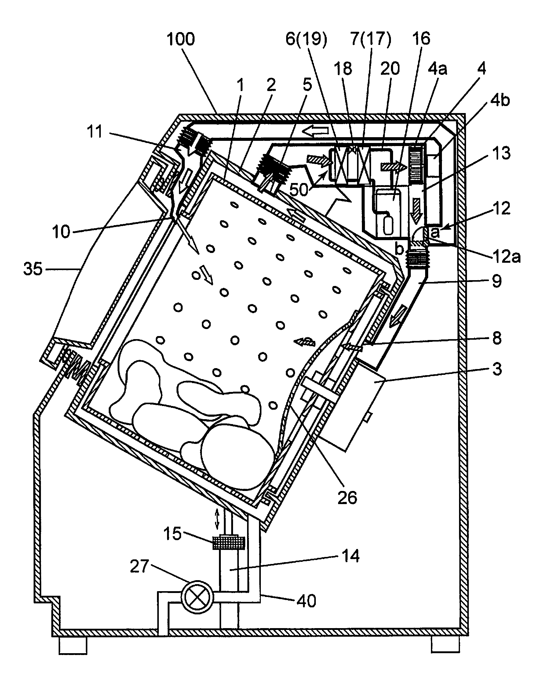
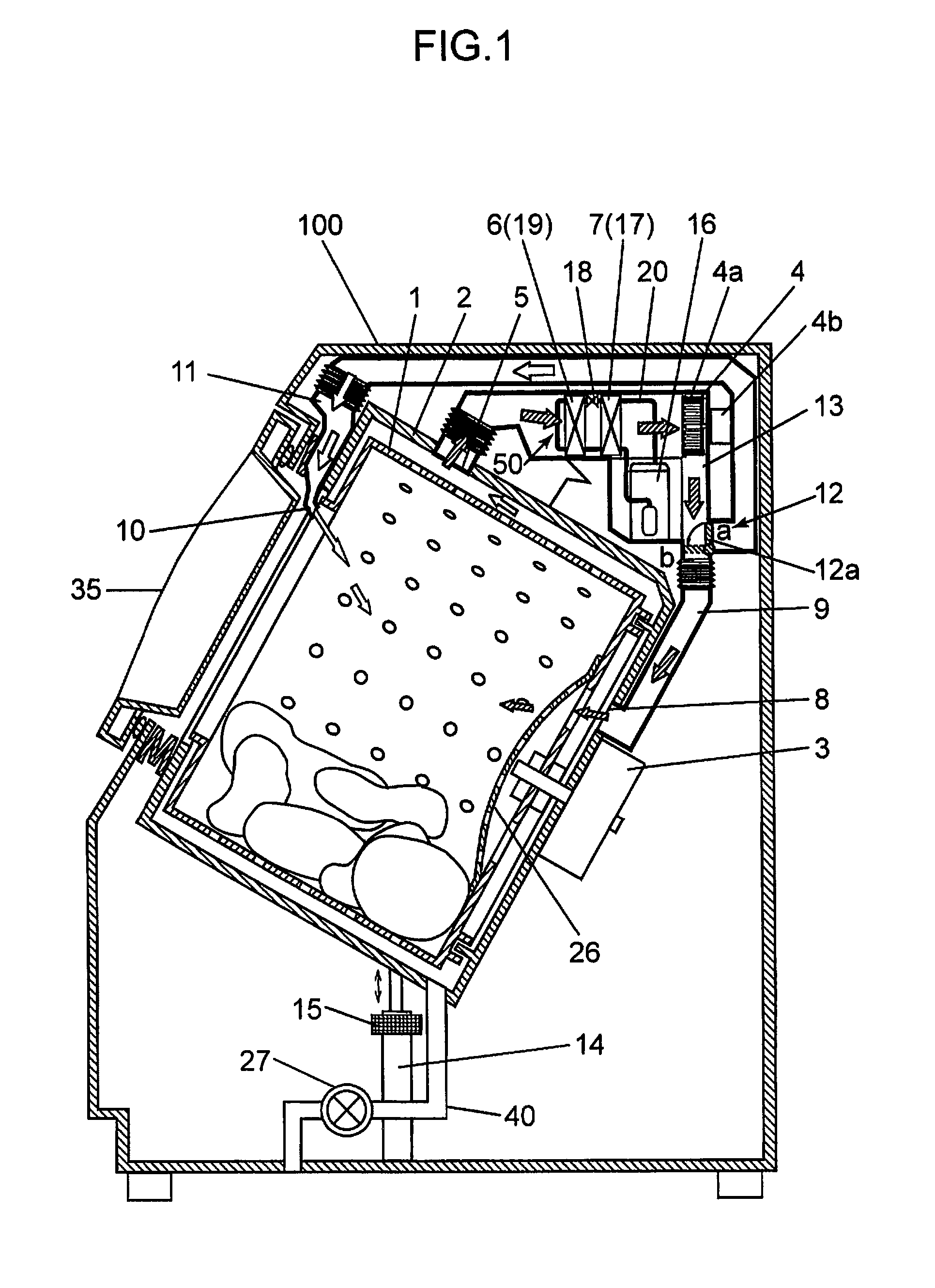
[0029]FIG. 1 is a lateral cross sectional view of the drum-type washer dryer according to one embodiment of the present invention.

[0030]In FIG. 1, a cylindrical drum 1, (storage portion), which opens forward and has a bottom surface to store laundry, is supported inside the housing 100. The cylindrical drum 1 is stored in a cylindrical water tub 2 which stores wash water. A drum drive motor 3 (drum driver) is mounted on the rear surface of the water tub 2. The drum drive motor 3 rotates the drum 1 around the rotating axis which is inclined upward to the front.

[0031]The housing 100 is provided with a door 35 which faces the open-end side of the drum 1, so that a user may open the doo...

embodiment 2

[0111]Embodiment 2 of the present invention is described in detail with reference to the drawings.

[0112]Since the basic configuration of the drum-type washer dryer according to Embodiment 2 is the same as the drum-type washer dryer shown in FIG. 1, the same reference numerals are given to the common components, and the explanation thereof is omitted as appropriately.

[0113]As shown in FIG. 7, the drum-type washer dryer of this embodiment includes a controller 170. Like the drum-type washer dryer according to Embodiment 1, the controller 170 controls a series of operations such as washing, rinsing, spin-drying and drying based on setting information, which is input by the user via a setup interface 32, and monitored operational conditions of each component. For example, the controller 170 controls the rotation of the drum drive motor 3 via the motor drive circuit 22 and operations of the blower 4 and the heat pump device 50 in the drying process. The controller 170 also controls the d...


PUM


Abstract

A laundry dryer has drum (1) which stores laundry; heat pump device including pipeline connecting compressor (16), which compresses refrigerant, radiator (17), pressure reducer (18), which reduces refrigerant after heat emission at radiator (17), and heat absorber (19), so that pipeline allows sequential circulation of refrigerant; circulation duct (13) in which blower (4) is situated to blow dry air so that dry air sequentially circulates from drum (1), heat absorber (19), radiator (17), to drum (1) again; air volume controller which controls blower (4) to adjust dry air volume in circulation duct (13); and compressor controller which controls rotational speed of compressor (16), wherein compressor controller changes rotational speed of compressor (16) based on fluctuation in dry air volume in circulation duct (13).

Description

BACKGROUND OF THE INVENTION[0001]1. Field of the Invention[0002]The present invention relates to a laundry dryer which dries laundry and a washer dryer which has functions to wash and dry the laundry.[0003]2. Description of the Related Art[0004]A conventional drum-type washer dryer as shown in FIG. 11 blows dry air at high temperature and low humidity, from a blower 104 into a drum 103, which is enclosed in an outer tank 102 elastically supported in a main body 101. The dry air dries laundry in the drum 103. A heater is used as means for heating the dry air.[0005]Patent Document 1 discloses that an increase in volume or velocity of the dry air blown into the drum 103 effectively works to reduce wrinkles during a drying process. If power consumption by the blower is decreased, the blower 104 has to decrease the dry air volume as appropriate. For example, the blower 104 may change the rotational speed to change the air volume.[0006]In recent years, a heat pump device 105 as shown in F...

Claims


Application Information

Patent Timeline
Patent Type & Authority Applications(United States)
IPC IPC(8): D06F35/00F26B11/02
CPCD06F25/00D06F58/02D06F58/206Y02B40/72D06F2058/2864D06F2058/287D06F58/28D06F2103/50D06F2105/26D06F2103/36D06F2105/24D06F58/30Y02B40/00D06F2103/54D06F58/50
Inventor TANIGUCHI, MITSUNORIFUJIWARA, NORIHIKONAKAMOTO, SHIGEHARUKANG, AHIN
Owner PANASONIC CORP
Why Eureka
Try Eureka