Rotary switch mechanism

a rotary switch and mechanism technology, applied in the direction of electric switches, basic electric elements, electric apparatus, etc., can solve the problems conventional rotary switch mechanisms b>2/b> failing to meet user requirements, etc., and achieve the effect of reducing the possibility of erroneous operation problems

Inactive Publication Date: 2012-07-26
PRIMAX ELECTRONICS LTD
View PDF4 Cites 40 Cited by
  • Summary
  • Abstract
  • Description
  • Claims
  • Application Information

AI Technical Summary

Benefits of technology

[0010]The present invention also provides a rotary switch mechan

Problems solved by technology

For example, since the conventional rotary switch mechanism 2 can execute at most four commands, the conventional rotary swit

Method used


Image

  • Rotary switch mechanism
  • Rotary switch mechanism
  • Rotary switch mechanism

Examples


Embodiment Construction

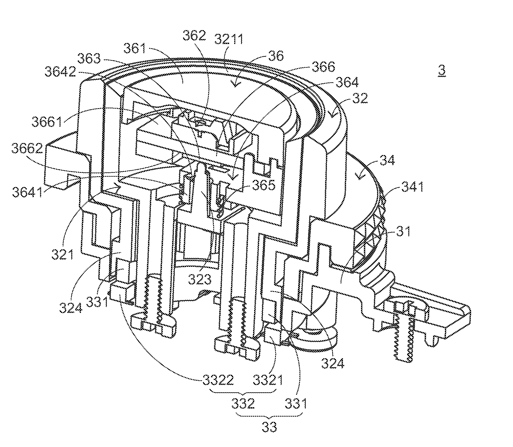
[0031]FIG. 4 is a schematic perspective view illustrating the outward appearance of a rotary switch mechanism according to an embodiment of the present invention. As shown in FIG. 4, the rotary switch mechanism 3 comprises a main circuit board 30, a base 31, a first rotatable member 32, a second rotatable member 34 and a push button 36. The base 31 is disposed on the main circuit board 30. The first rotatable member 32 is disposed on the base 31. The second rotatable member 34 is disposed on the base 31 and arranged around the first rotatable member 32. In addition, the second rotatable member 34 is rotatable with respect to the base 31. The push button 36 is disposed within the first rotatable member 32. In addition, the push button 36 has a pushing surface 361. The user's finger is movable on the pushing surface 361 of the push button 36. In the rotary switch mechanism 3, the outer surface of the first rotatable member 32 is a smooth surface. In addition, the outer surface of the ...


PUM


Abstract

A rotary switch mechanism includes a first rotatable member, a second rotatable member, a push button and a triggered switch. By rotating the first rotatable member, a first rotation command is executed. By rotating the second rotatable member, a second rotation command is executed. By moving a user's finger on the push button, a motion command is executed. By pressing down the push button to trigger the push switch, a pushing command is executed. In such way, the rotary switch mechanism may be used to input plural commands.

Description

FIELD OF THE INVENTION[0001]The present invention relates to a rotary switch mechanism, and more particularly to a rotary switch mechanism with a push button function.BACKGROUND OF THE INVENTION[0002]Generally, a rotary switch mechanism is a mechanism that is rotated in either a clockwise direction or an anti-clockwise direction. For example, the rotary switch mechanism is usually installed on an acoustical device for adjusting sound volume or changing broadcast channels.[0003]With the increasing development of science and technology, the applications of the rotary switch mechanism are gradually expanded. Generally, as shown in FIG. 1, the rotary switch mechanism 10 is installed on a keyboard device 1 of a computer system in order to enhance the function of the keyboard device 1. By operating the rotary switch mechanism 10, a sound volume adjustment command of a video player program, a text file proportional scale command or an image file proportional scale command in the computer s...

Claims


Application Information

Patent Timeline
IPC IPC(8): H01H9/00
CPCH01H25/008
Inventor WU, CHUN-CHESU, CHUN-NAN
Owner PRIMAX ELECTRONICS LTD
Why Eureka
Try Eureka