
Converging blocker door system for use with a thrust reverser

a technology of blocker doors and reversers, which is applied in the direction of vessel construction, marine propulsion, aircraft navigation control, etc., can solve the problems that the optimal reverse thrust cannot be achieved with the conventional thrust reverser blocker doors, and achieve the effect of reducing the weight of translating elements, and shortening the stroke length

Inactive Publication Date: 2012-07-26
SPIRIT AEROSYSTEMS
View PDF2 Cites 9 Cited by
  • Summary
  • Abstract
  • Description
  • Claims
  • Application Information

AI Technical Summary

Benefits of technology

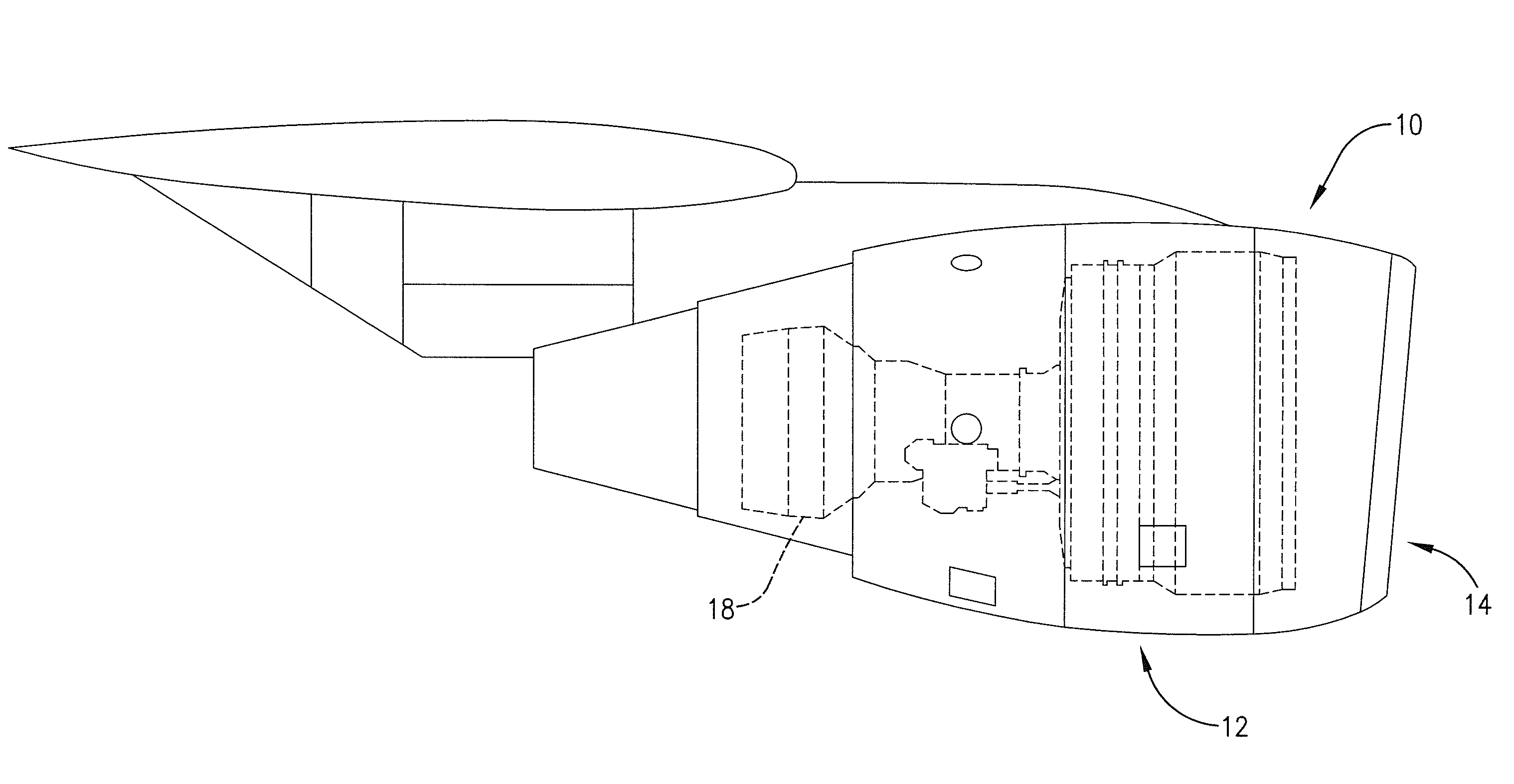
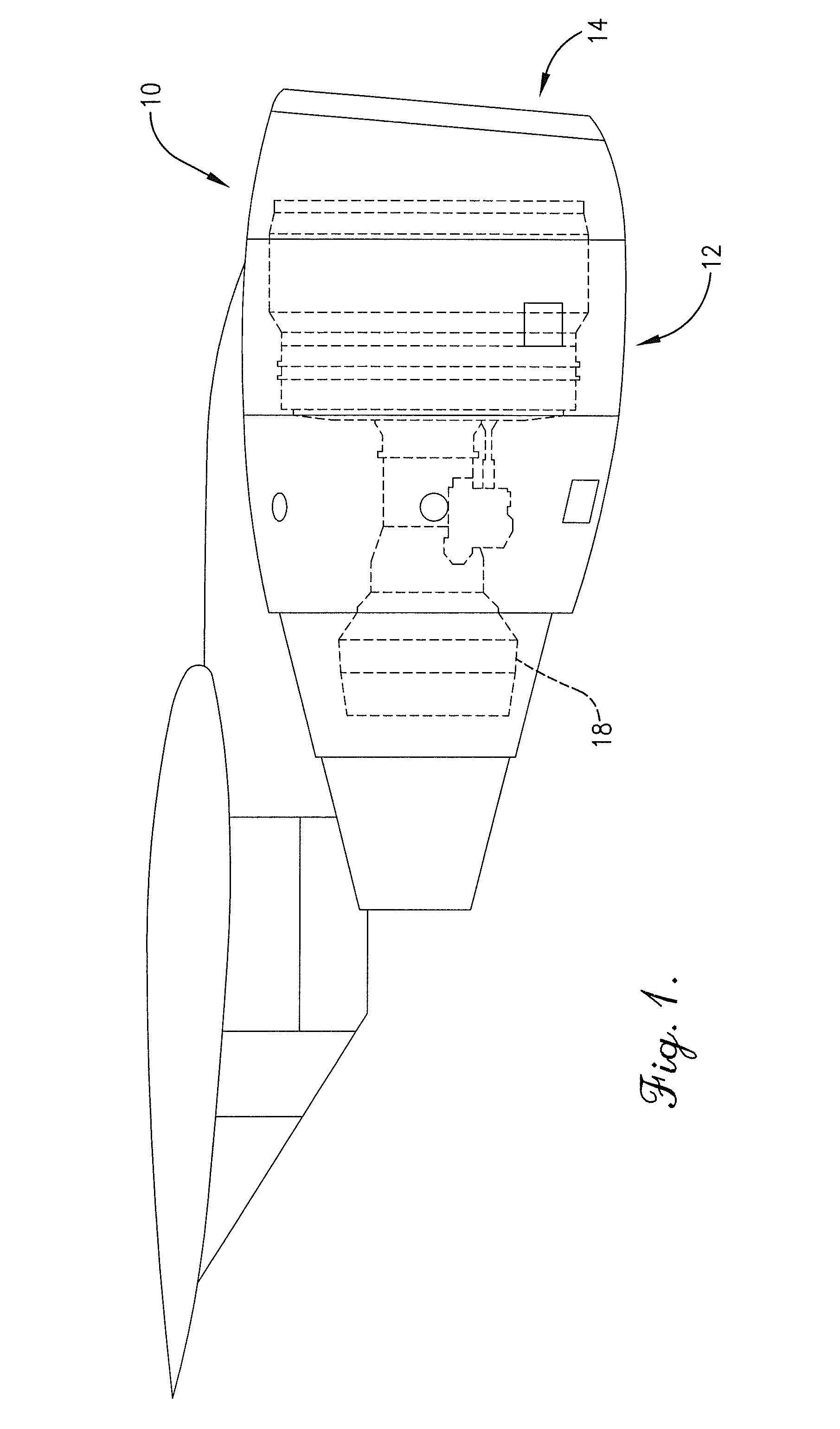
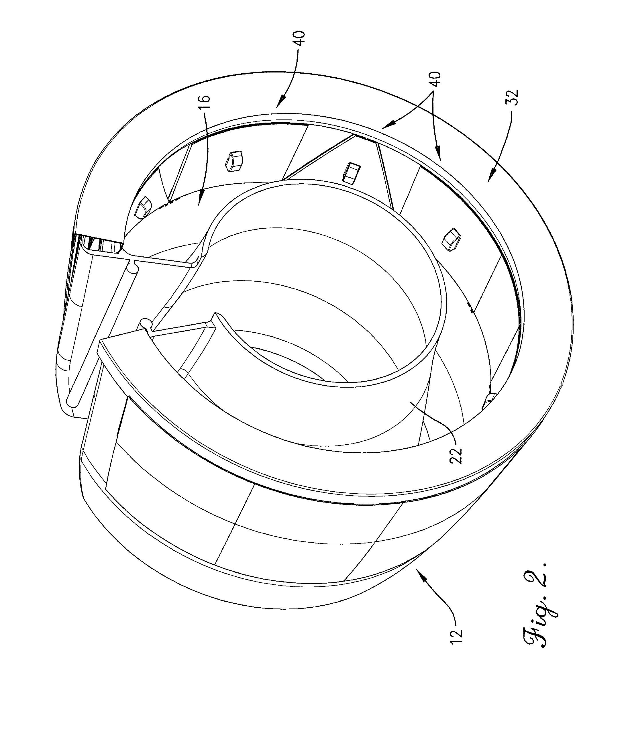
[0008]Embodiments of the present invention provide a blocker door system for use with an aircraft engine thrust reverser that includes a plurality of cascade elements. The system may broadly comprise a push ring, a plurality of connecting rods, a plurality of crankshafts, a plurality of blocker doors, and a plurality of linking elements. The push ring may encircle the aircraft engine. The connecting rods may connect along the circumference of the push ring. The crankshafts may rotatably couple to the connecting rods and the blocker doors. The linking elements may connect one blocker door to the adjacent blocker door and may be operable to guide the motion of the blocker doors relative to one another.
[0011]The mating features of the converging blocker door system allow the quick deployment of the doors over a substantially shorter stroke than conventional blocker door-diaphragm / translating sleeve systems with traditional drag links anchored to a fixed inner structure. The absence of a translating diaphragm in this concept combined with the placement of the cascades further outboard from the engine centerline creates the opportunity for a substantially shortened stroke length and less weight of the translating elements at equivalent or better reverser efficiencies. It can also be appreciated that the absence of drag links in the fan duct flow would further improve engine performance.

Problems solved by technology

However, gaps form between the sides of the blocker doors which allows some air to pass through the blocker doors.
Thus, optimal reverse thrust may not be achieved with conventional thrust reverser blocker doors.

Method used


Image

  • Converging blocker door system for use with a thrust reverser
  • Converging blocker door system for use with a thrust reverser
  • Converging blocker door system for use with a thrust reverser

Examples


first embodiment

[0055]In the blocker doors 64, as seen in FIGS. 7-10, each blocker door 64 may include an inner flange 66 on the first side 54 and an outer flange 68 on the second side 56. The inner flanges 66 may have a complementary and reciprocal shape to the outer flanges 68. Generally, the inner flange 66 on the first side of one blocker door 64 overlaps the outer flange 68 on the second side 56 of an adjacent blocker door 40. When the blocker doors 40 are deployed, the blocker doors 64 are at maximum overlap such that the inner flanges 66 overlap the outer flanges 68 nearly completely, as seen in FIGS. 7-8.

[0056]The linking element 42 generally links the blocker doors 64 together to prevent the one blocker door 64 from decoupling from the adjacent blocker door 64, and guides the motion of the blocker doors 64 relative to one another during deployment of the thrust reverser 20. A first embodiment of the linking element 70 may include a cylindrical slider 72 and an attach pin 74 positioned ther...

second embodiment

[0058]In the blocker door 80, the first side 54 of one blocker door 80 may interleave with the second side 56 of an adjacent blocker door 80, as seen in FIGS. 12-15. The mating features 62 of the blocker door 80 may include a tongue 82 extending along the center of the length of the first side 54, and a groove 84, complementary to the tongue 82, formed by an upper tab 86 and a spaced-apart lower tab 88 extending along the center of the length of the second side 56. The tongue 82, the upper tab 86, the lower tab 88, and by extension the groove 84 all increase in width from the top edge 58 to the bottom edge 60. Each blocker door 80 may include a tongue 82 on the first side 54 and a groove 84 on the second side 56, such that the tongue 82 of one blocker door 80 fits into the groove 84 of the adjacent blocker door 80.

[0059]A second embodiment of the linking element 90 may include a threaded fastener 92, a horizontal roller 94, and a vertical roller 96, as seen in FIG. 16. The threaded ...


PUM


Abstract

A blocker door system to be used with an aircraft engine thrust reverser comprises a push ring, a plurality of connecting rods, a plurality of crankshafts, a plurality of blocker doors, and a plurality of linking elements. The push ring may encircle the aircraft engine. The connecting rods may connect along the circumference of the push ring. The crankshafts may rotatably couple to the connecting rods. The blocker doors may be positioned adjacent one another around the circumference of the aircraft engine wherein at least a portion of one blocker door covers at least a portion of the adjacent blocker door. The linking elements may connect one blocker door to the adjacent blocker door and may be operable to guide the motion of the blocker doors relative to one another.

Description

BACKGROUND OF THE INVENTION[0001]1. Field of the Invention[0002]Embodiments of the present invention relate to aircraft engine thrust reversers. More particularly, embodiments of the present invention relate to blocker doors for use with cascade-type aircraft engine thrust reversers.[0003]2. Description of the Related Art[0004]Cascade thrust reversers are often employed in aircraft under-wing bypass-type engines and may include blocker doors located along the outer circumferential wall of the bypass fan duct, such that when the thrust reverser is deployed, the blocker doors are actuated inward to redirect the flow of air in the bypass fan duct to flow through the cascades—thereby providing reverse thrust. The blocker doors often have an isosceles trapezoid shape with a broad base, a narrower top, and two angled sides. The doors, when stowed, are typically positioned in line with the outer wall of the fan duct, such that the base is pointed in the forward direction and the top is poi...

Claims


Application Information

Patent Timeline
Patent Type & Authority Applications(United States)
IPC IPC(8): B64D33/00
CPCB64D33/04
Inventor WELCH, JOHN MICHAELSAWYER, CHRISTOPHER STEVEN
Owner SPIRIT AEROSYSTEMS
Learn More