Inkjet printing apparatus

a technology of printing apparatus and inkjet, which is applied in the direction of printing and other printing apparatus, can solve the problems of increasing the size of the apparatus, and achieve the effect of high resistance to flow passag

Inactive Publication Date: 2012-07-26
RISO KAGAKU CORP
View PDF14 Cites 34 Cited by
  • Summary
  • Abstract
  • Description
  • Claims
  • Application Information

AI Technical Summary

Benefits of technology

[0008]In the case of a high-resolution inkjet head including densely arranged nozzles, ink flow passages inside the inkjet head are narrow and flow passage re

Problems solved by technology

However, this arrangement leads to an increase in size of the apparatus.
A similar

Method used


Image

  • Inkjet printing apparatus
  • Inkjet printing apparatus
  • Inkjet printing apparatus

Examples


modified example

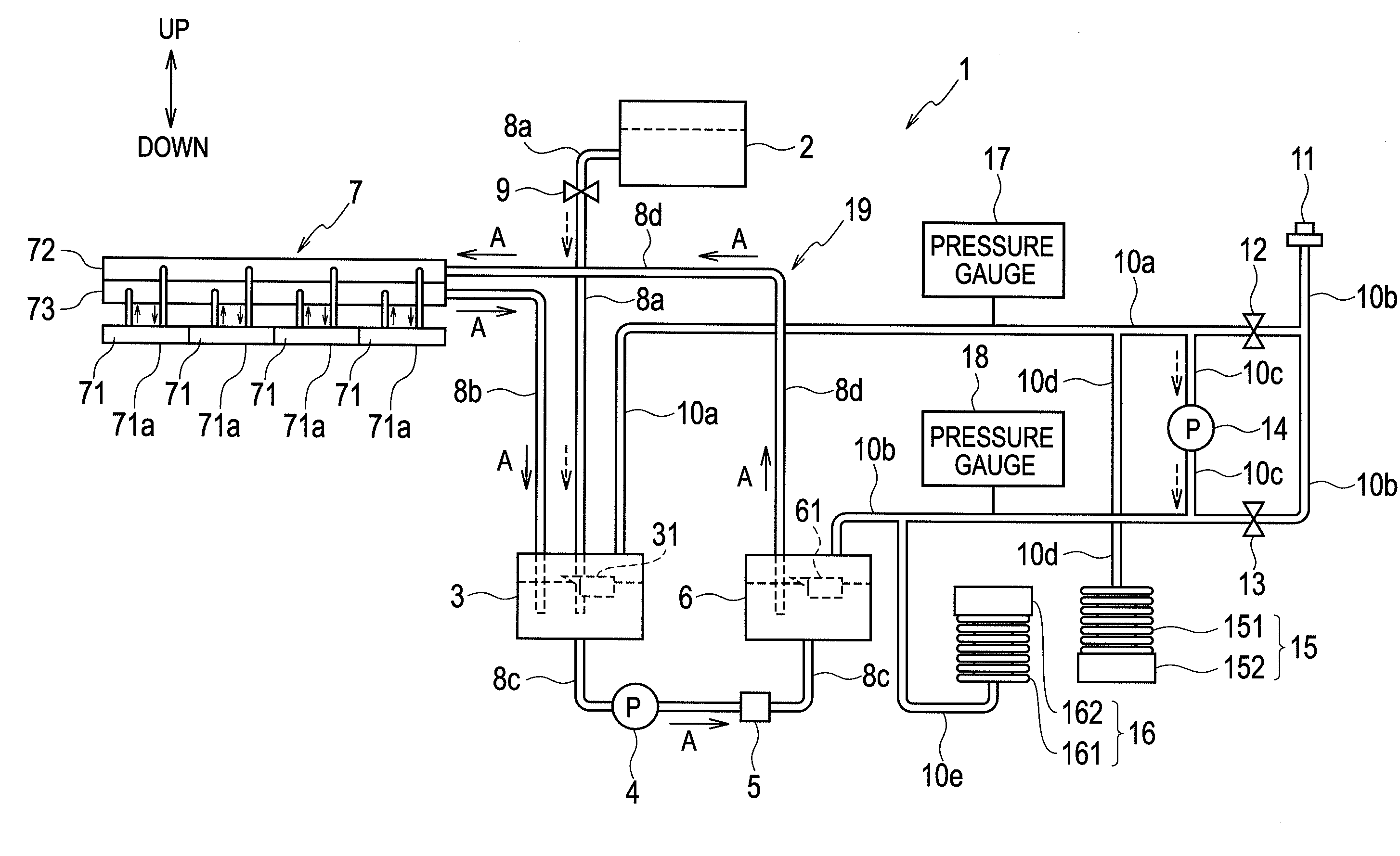
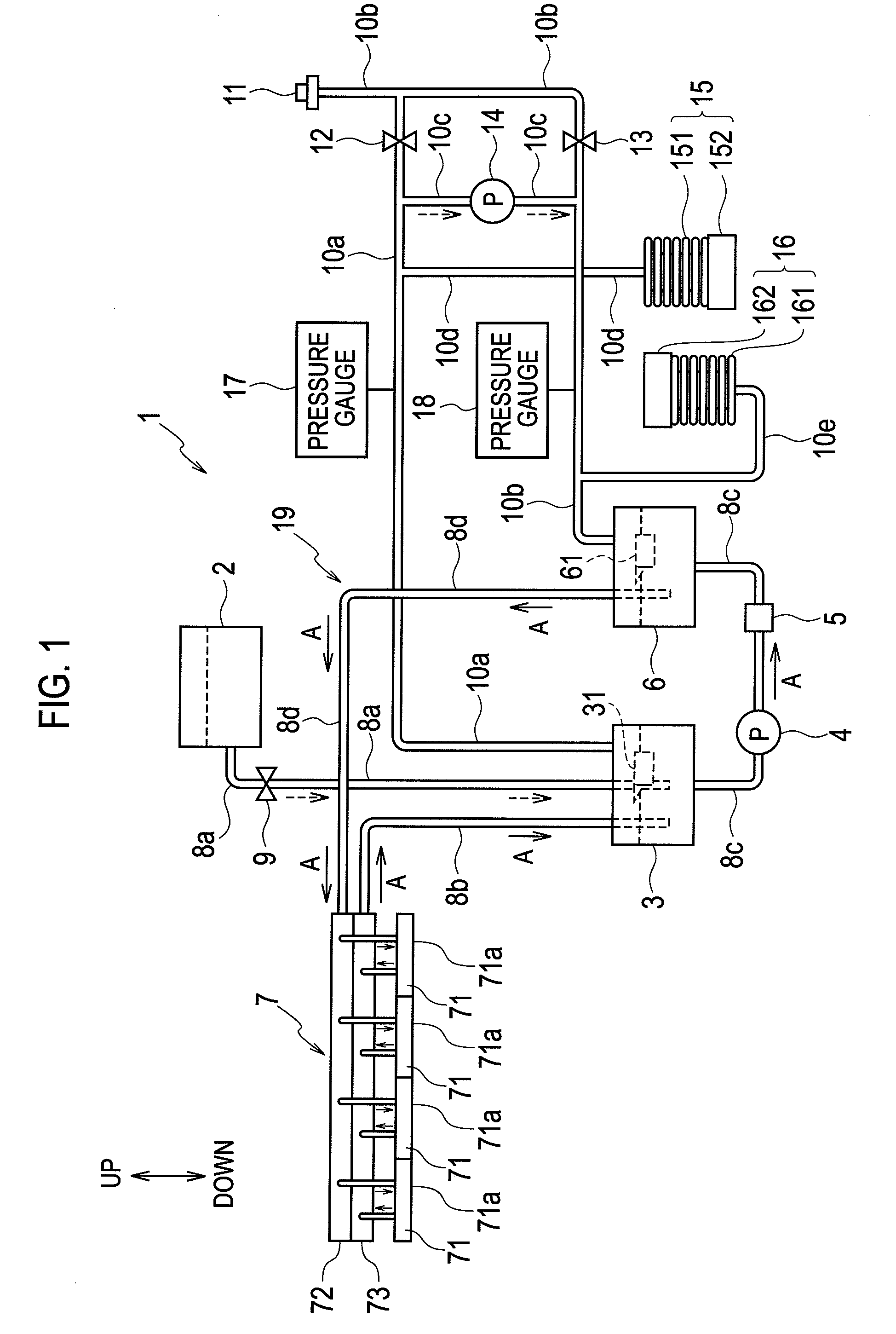
[0097]FIG. 5 is a schematic configuration diagram of an inkjet printing apparatus 1A according to a modified example of the embodiment of the present invention.

[0098]As shown in FIG. 5, the inkjet printing apparatus 1A according to this modified example adopts a configuration obtained by omitting the downstream tank pressure adjuster 15 and the upstream tank pressure adjuster 16 from the inkjet printing apparatus 1 shown in FIG. 1, and adding a pressure adjuster 21 (serving as the first and second pressure adjusters) instead.

[0099]FIG. 6 is a cross-sectional view showing a configuration of the pressure adjuster 21. FIG. 6 shows a cross section taken along a central axis of the pressure adjuster 21. The pressure adjuster 21 has the function as the first pressure adjuster configured to adjust the pressure inside the upstream tank 6 and the function as the second pressure adjuster configured to adjust the pressure inside the downstream tank 3 during circulation of the ink (during the p...


PUM


Abstract

An inkjet printing apparatus includes: an inkjet head configured to discharge ink; a first tank configured to store ink to be supplied to the inkjet head; a second tank configured to store ink not consumed by the inkjet head; an ink circulation path for circulation of ink among the first tank, the inkjet head, and the second tank; a pressurizer configured to provide the first and second tanks with a pressure for the circulation of ink through the ink circulation path; a first pressure adjuster configured to adjust a pressure inside the first tank during the circulation of ink; and a second pressure adjuster configured to adjust a pressure inside the second tank during the circulation of ink.

Description

CROSS REFERENCE TO RELATED APPLICATION[0001]This application is based upon and claims the benefit of priority from the prior Japanese Patent Application No. 2011-011703, filed on Jan. 24, 2011, the entire contents of which are incorporated herein by reference.BACKGROUND OF THE INVENTION[0002]1. Field of the Invention[0003]The present invention relates to an inkjet printing apparatus configured to make print on a printing medium by discharging ink from an inkjet head.[0004]2. Description of the Related Art[0005]An ink circulation type inkjet printing apparatus has heretofore been known.[0006]An ink circulation type inkjet printing apparatus in a related art disclosed in Japanese Unexamined Patent Application Publication No. 2009-297961 includes an inkjet head and ink tanks respectively located upstream and downstream of the inkjet head. These ink tanks are connected to each other through a pipe. An ink is supplied from the ink tank on the upstream side (an upstream tank) to the inkje...

Claims


Application Information

Patent Timeline
IPC IPC(8): B41J2/175
CPCB41J2/175B41J29/38B41J2/18
Inventor AKIYAMA, TOMOYUKISHINOHARA, MASAAKI
Owner RISO KAGAKU CORP
Why Eureka
Try Eureka