Position detection apparatus, position detection method, mobile, and receiver

a position detection and receiver technology, applied in the field of position detection apparatus, position detection method, mobile and receiver, can solve the problems of inability to identify the mobiles of the receiver, difficulty in identifying the ultrasonic wave corresponding to a certain infrared ray signal, and inability to detect coordinates normally

Active Publication Date: 2012-07-26
NEC CORP
View PDF8 Cites 54 Cited by
  • Summary
  • Abstract
  • Description
  • Claims
  • Application Information

AI Technical Summary

Benefits of technology

[0047]The present invention can provided a position detection apparatus, a position detection method, a mobile, and a receiver capab

Problems solved by technology

According to this method, in the case where plural mobiles are used simultaneously, the receiver cannot identify each of the mobiles.
Therefore, identification of the ultrasonic wave corresponding to a certain infrared ray signal is difficult and the coordinate cannot be detected normally

Method used


Image

  • Position detection apparatus, position detection method, mobile, and receiver
  • Position detection apparatus, position detection method, mobile, and receiver
  • Position detection apparatus, position detection method, mobile, and receiver

Examples


embodiment 1

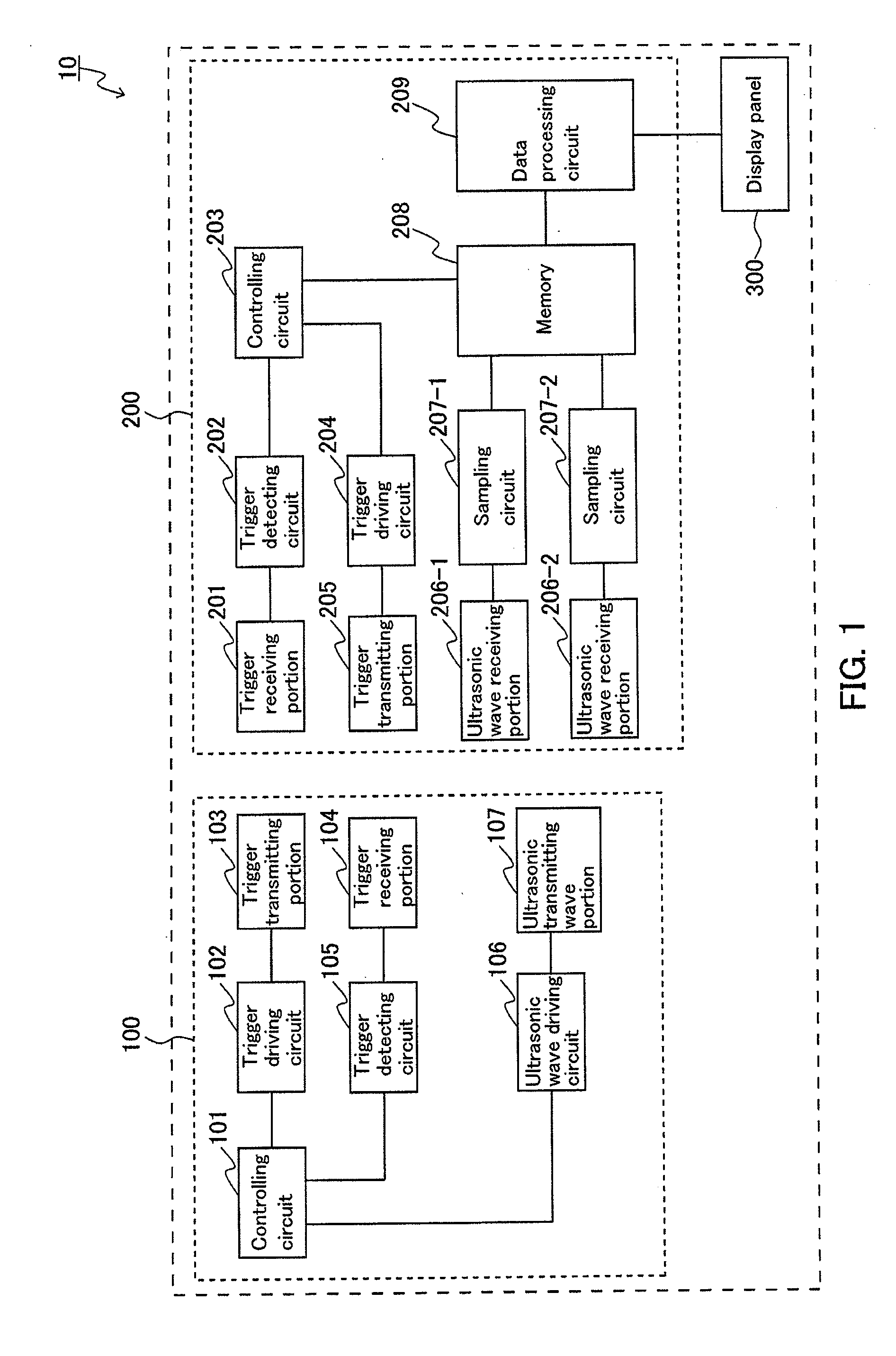
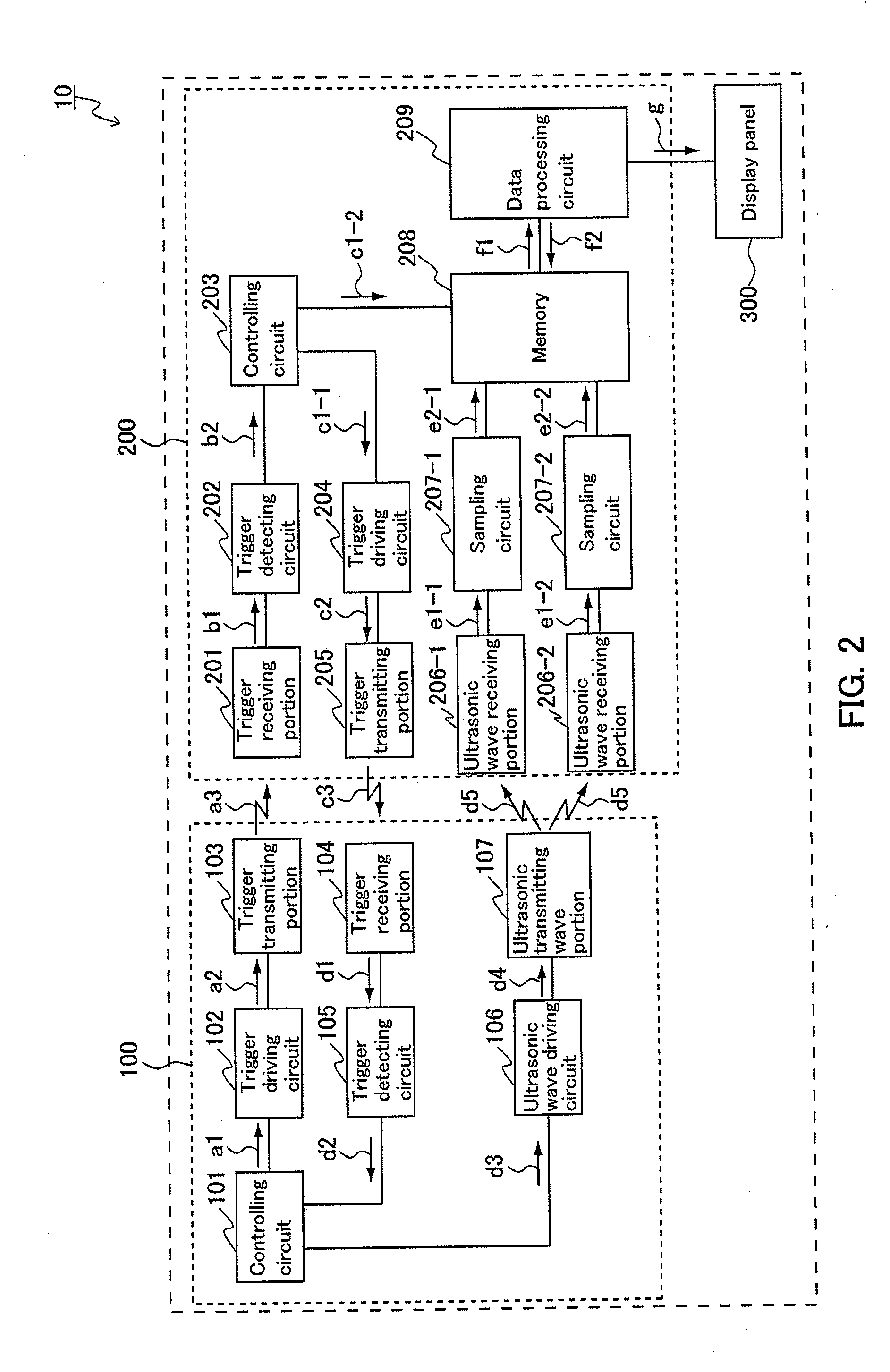
[0057]FIGS. 1 and 2 each show an example of the configuration of the position detection apparatus according to this Embodiment. As shown in FIGS. 1 and 2, this position detection apparatus 10 is provided with a mobile 100, a receiver 200, and a display panel 300. The receiver 200 is provided at a predetermined position distanced from the mobile 100, and the display panel 300 displays the path of the mobile 100. The display panel 300 may be a monitor commonly used, a large-screen display such as a liquid crystal display or a plasma display, or a projected screen projected by a projector.

[0058]The mobile 100 is provided with a controlling circuit 101, a trigger driving circuit 102, a trigger transmitting portion 103, a trigger receiving portion 104, a trigger detecting circuit 105, an ultrasonic wave driving circuit 106, and an ultrasonic wave transmitting portion 107. The controlling circuit 101 is electrically connected to the trigger driving circuit 102, the trigger detecting circu...

embodiment 2

[0084]Next, with reference to FIG. 4, the position detection method in a case where plural mobiles are used will be described. In this Embodiment, the case in which two mobiles 100a and 100b are used will be described.

[0085]The mobile 100a transmits a trigger signal of requesting transmitting ultrasonic wave to the receiver 200 at the time of requesting position detection. When the receiver 200 receives the trigger signal of requesting transmitting ultrasonic wave from the mobile 100a, it checks the receipt status of the ultrasonic wave from the other mobile 100b. If it is not under a status of receiving the ultrasonic wave from the mobile 100b, the receiver 200 transmits allowance of transmitting ultrasonic wave by a trigger signal to the mobile 100a from which the receiver 200 has received the request for transmitting ultrasonic wave. Since each mobile transmits a signal that can be identified, the receiver can identify from which mobile the signal has been transmitted. A certain ...

embodiment 3

[0090]In the following embodiment, the case in which the position detection apparatus of the present invention is applied to an electronic pen system will be described.

[0091]In this Embodiment, the mobile that configures the position detection apparatus of the present invention is an electronic pen. The electronic pen is an input device that senses the position of the pen tip in real time by transmitting a signal from the pen tip and receiving the signal with the receiver. The path may be displayed on the display panel by scanning on the display panel or may be displayed on the display panel by scanning on a scanning region other than the display panel.

[0092]FIG. 5 shows an example of the configuration of the position detection apparatus according to this Embodiment. As shown in FIG. 5, the position detection apparatus of this Embodiment is provided with an electronic pen, a receiver provided at a predetermined position distanced from the electronic pen, and a display panel that dis...


PUM


Abstract

To detect the positions of the respective mobiles correctly without being affected by the ultrasonic waves from other mobile(s) in a case where plural mobiles are used simultaneously.
The mobile comprises a unit that transmits a trigger signal of requesting transmitting ultrasonic wave that is capable of identifying the mobile, a unit that receives a trigger signal of allowing transmitting ultrasonic wave from the receiver, and a unit that transmits an ultrasonic wave immediately upon receipt of the trigger signal of allowing transmitting ultrasonic wave. The receiver comprises a unit that receives a trigger signal of requesting transmitting ultrasonic wave from the mobile, a unit that transmits a trigger signal of allowing transmitting ultrasonic wave that can be identified at the mobile side, a control unit that controls a transmitting timing of the trigger signal of allowing transmitting ultrasonic wave, at least two ultrasonic wave receiving units provided at predetermined gaps, a unit that calculates an ultrasonic wave propagation time from the mobile based on a time of transmitting the trigger signal of allowing transmitting ultrasonic wave and an ultrasonic wave arrival time, and a position calculation unit that calculates a position of the mobile based on the ultrasonic wave propagation time calculated.

Description

TECHNICAL FIELD [0001]The present invention relates to a position detection apparatus, a position detection method, a mobile, and a receiver.BACKGROUND ART [0002]Methods and apparatuses of detecting the positions of mobiles such as a mobile robot and coordinate input devices such as an electronic pen and the like by using an ultrasonic wave and measuring the propagation time thereof have been proposed (see, for example, Patent Documents 1 to 3). In the position detection method utilizing the propagation time of ultrasonic wave, a mobile transmits an ultrasonic wave and an infrared ray at the same time at regular intervals and a receiver receives them. FIG. 7 shows an example of the signal detected by the receiver. In this example, the ultrasonic wave transmitted from the mobile is a signal of burst waveform and the signal of the same waveform is transmitted for every transmitting intervals. Since there is the difference in speed between the ultrasonic wave and the infrared ray, a ti...

Claims


Application Information

Patent Timeline
IPC IPC(8): G01S15/06
CPCG06F3/0433G01S11/16
Inventor MIYAMOTO, JUNICHIKAJITANI, HIROSHI
Owner NEC CORP
Why Eureka
Try Eureka