Line-of-sight detection apparatus and method thereof

a detection apparatus and line-of-sight technology, applied in the field of line-of-sight estimation technology, can solve the problems of significant decrease in the detection accuracy of line-of-sight, and achieve the effect of accurate detection of line-of-sigh

Active Publication Date: 2012-07-26
CANON KK
View PDF10 Cites 32 Cited by
  • Summary
  • Abstract
  • Description
  • Claims
  • Application Information

AI Technical Summary

Benefits of technology

[0006]The present invention is directed to a line-of-sight detection apparatus that can accurately detect the line of sight without being affected by hidden eyes or the dominant eye.

Problems solved by technology

However, one of the problems with the conventional technology is a significant decrease in the line-of-sight detection accuracy that may be caused, for example, when the face turns sideways and one of the eyes is hidden or when the eyes are hidden by hair.
Another problem is caused by the dominant eye.

Method used


Image

  • Line-of-sight detection apparatus and method thereof
  • Line-of-sight detection apparatus and method thereof
  • Line-of-sight detection apparatus and method thereof

Examples


Embodiment Construction

[0034]Various exemplary embodiments, features, and aspects of the invention will be described in detail below with reference to the drawings.

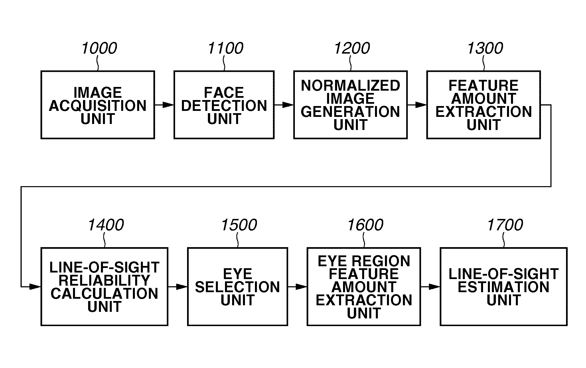
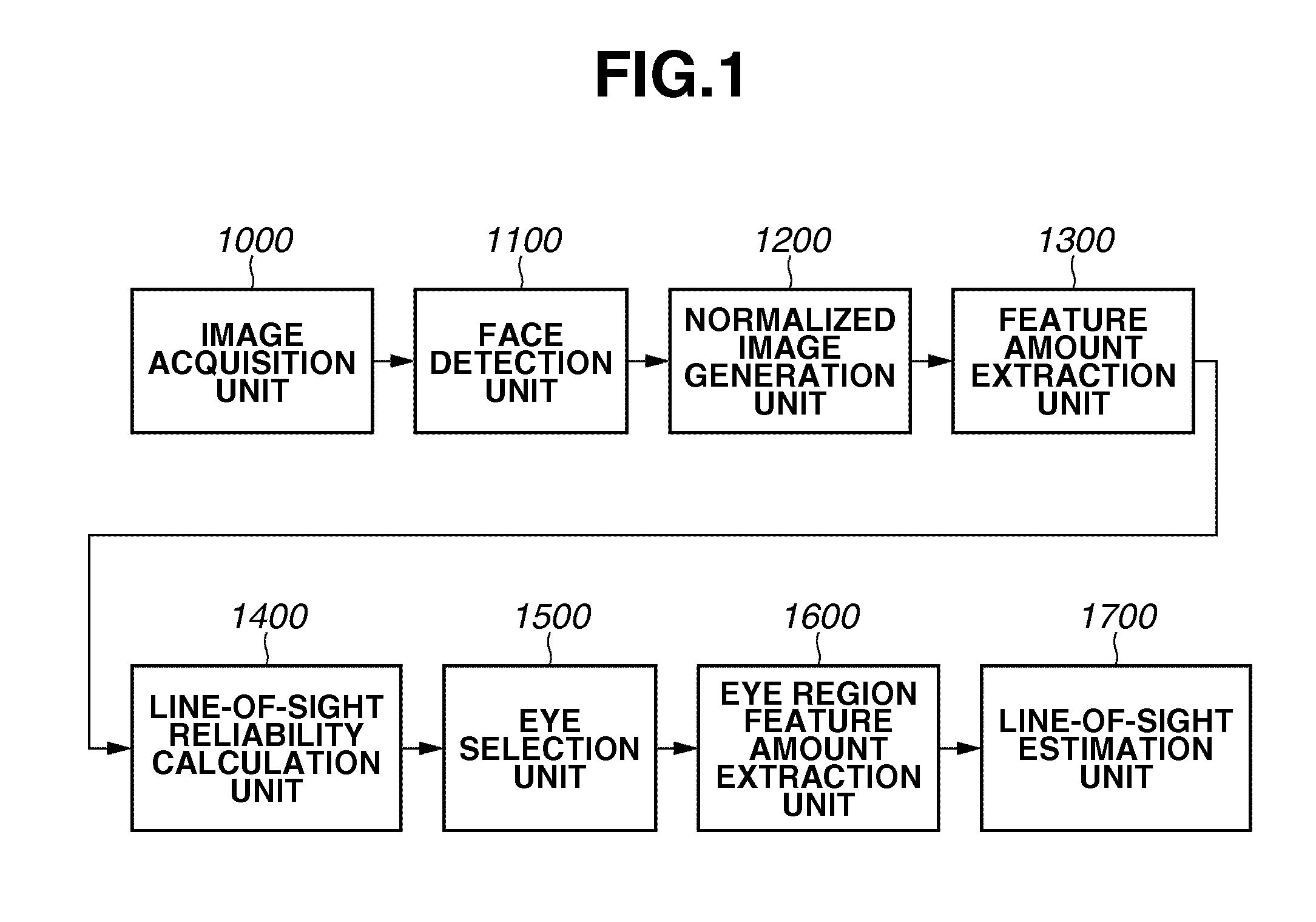
[0035]FIG. 1 is a diagram illustrating the functional configuration of a line-of-sight detection apparatus in a first exemplary embodiment of the present invention. The functional configuration illustrated in FIG. 1 is the configuration implemented by downloading the line-of-sight detection program of the present exemplary embodiment into the memory for execution by the central processing unit (CPU).

[0036]As illustrated in FIG. 1, the line-of-sight detection apparatus in the present exemplary embodiment includes an image acquisition unit 1000, a face detection unit 1100, a normalized image generation unit 1200, a feature amount extraction unit 1300, a line-of-sight reliability calculation unit 1400, an eye selection unit 1500, an eye region feature amount extraction unit 1600, and a line-of-sight estimation unit 1700. The image acquisition unit...


PUM


Abstract

A line-of-sight detection apparatus includes a detection unit configured to detect a face from image data, a first extraction unit configured to extract a feature amount corresponding to a direction of the face from the image data, a calculation unit configured to calculate a line-of-sight reliability of each of a right eye and a left eye based on the face, a selection unit configured to select an eye according to the line-of-sight reliability, a second extraction unit configured to extract a feature amount of an eye region of the selected eye from the image data, and an estimation unit configured to estimate a line of sight of the face based on the feature amount corresponding to the face direction and the feature amount of the eye region.

Description

BACKGROUND OF THE INVENTION[0001]1. Field of the Invention[0002]The present invention relates to a technology for estimating the line of sight of a person in an image.[0003]2. Description of the Related Art[0004]Conventionally, a technology for determining the line of sight of a person is known in which a face image including the black and the outer corner of the right and left eyes are used (for example, see Japanese Patent Application Laid-Open No. 2003-256852). However, as illustrated in FIG. 24, this conventional technology estimates only the eye direction α1 but does not consider the face direction β1. On the other hand, another technology is known in which the feature points of organs, such as the eye, are detected from the face in the image data and, using the distance between the detected feature points, the line of sight direction is estimated from both the eye direction al and the face direction β1 (for example, see Japanese Patent Application Laid-Open No. 2007-265367).[0...

Claims


Application Information

Patent Timeline
Patent Type & Authority Applications(United States)
IPC IPC(8): G06K9/46H04N5/225
CPCA61B3/113G06K9/00604G06T2207/30201G06T7/0042G06T7/73G06V40/19
Inventor KANEDA, YUJIMATSUGU, MASAKAZUMORI, KATSUHIKO
Owner CANON KK
Why Eureka
Try Eureka