Latching System For Securing An Implement To A Carrier Mounted To A Lifting Arm

a technology for securing systems and implements, which is applied in the direction of rod connections, couplings, manufacturing tools, etc., can solve the problems of partially latched implements, increased costs, and the securing rods moving to the unlatched position, and achieves compact and reliable

Active Publication Date: 2012-07-26
DEERE & CO
View PDF1 Cites 17 Cited by
  • Summary
  • Abstract
  • Description
  • Claims
  • Application Information

AI Technical Summary

Benefits of technology

[0006]An object of the invention is to provide a remotely operated latching system which is compact and reliable.

Problems solved by technology

One drawback associated with the patented designs is that a failure of the biasing mechanism when the implement is attached to the boom could result in the latch rod migrating to its unlatched position.
Another drawback of the patented designs is that an operator may not be aware if the latching rod arrangement becomes jammed or the like resulting in a partially latched implement.
Further, while hydraulic cylinders are effective devices for moving the latching rod arrangements to their unlatched positions, hydraulic fluid leakage is always a problem and the provision of hydraulic hoses and control valves often take up valuable space and require special design considerations resulting in increased cost.

Method used


Image

  • Latching System For Securing An Implement To A Carrier Mounted To A Lifting Arm
  • Latching System For Securing An Implement To A Carrier Mounted To A Lifting Arm
  • Latching System For Securing An Implement To A Carrier Mounted To A Lifting Arm

Examples


Embodiment Construction

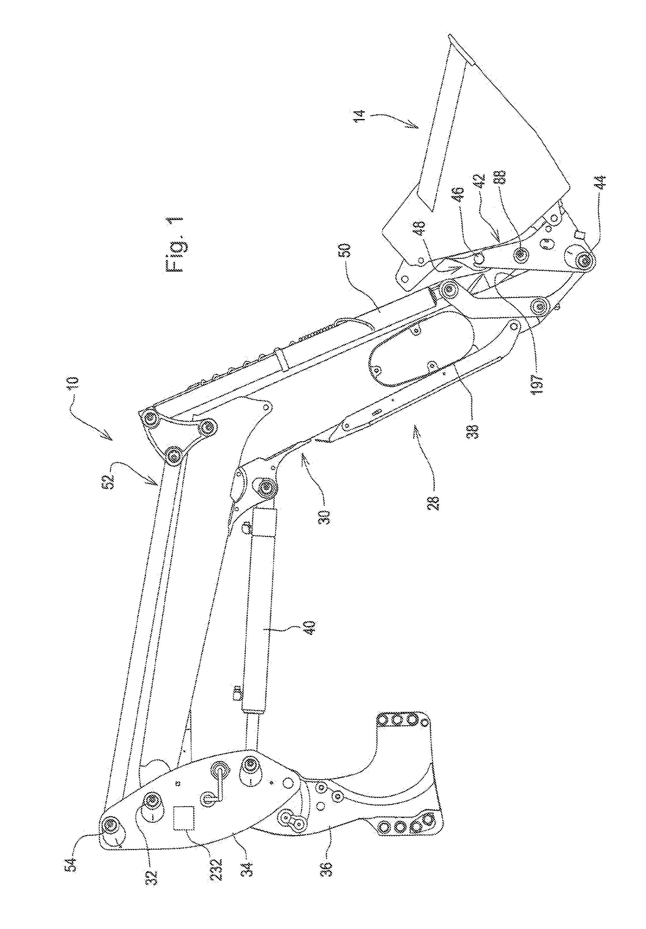
[0020]Referring now to FIG. 1, there is shown a front end loader 10 equipped with an attachment in the form of a bucket 14. However, it is to be understood that the present invention may be used with other loaders and / or attachments.

[0021]The loader includes a boom 28 comprising left and right, transversely spaced, fore-and-aft extending arms (only right arm 30 being shown) disposed for extending along opposite sides of a tractor (not shown) and each having a rear end pivotally attached, as by a pin 32, to an upper region of a respective one of a pair of upright masts 34, the masts 34, in turn, being fixed to respective upper regions of a pair of upright mounting frames 36 located on opposite sides of, and having lower regions fixed to a frame (not shown) of the tractor. The boom 28 further includes a cross tube (not visible) having opposite ends projecting through, and joining the arms 30 together at a location forwardly of the tractor, with caps 38 being mounted on outer faces of ...


PUM


Abstract

A remotely operable latching system is provided for securing an implement to a carrier mounted to a forward end of a lifting arm for pivoting about a horizontal tilt axis. The latching system is mounted to the carrier and includes a latching rod arrangement operated by an extensible and retractable linear electric motor between a retracted latching position and an extended unlatching position. A secondary latch arrangement is provided for rotating the latching rod arrangement to an arrested position preventing movement of the rod arrangement to its latching position once the latching rod is extended to its unlatching position. Movement of the rod arrangement to its arrested position is aided by a spring and by the electric motor. Release of the rod arrangement from the arrested position is done by rolling the carrier back towards the lifting arms bringing the latching rod arrangement into contact with the arm so as to pivot the rod arrangement out of its arrested position. A microprocessor based control unit is coupled to the electric motor and acts in response to a boom height input signals to prevent operation of the motor when the boom is above a preset height. Further, an LED indicator light operates in certain modes which apprise the operator of various operating conditions. For example, the LED light blinks slowly when the latching rod arrangement is being extended to its unlatch position, blinks rapidly if the latching rod jams causing an overload condition and gives a steady light when the latching rod arrangement is fully extended. Various timing requirements are also programmed into the control unit.

Description

FIELD OF THE INVENTION[0001]The present invention relates to an arrangement for securing an implement to a carrier mounted to lifting arms, particularly those of a front loader boom, where the implement and carrier can be fastened to each other by movable latch rods that can be moved between latched and unlatched positions either manually or by a remotely controlled motor.BACKGROUND OF THE INVENTION[0002]A known type of latch arrangement for securing an implement to a carrier mounted to lifting arms of a boom comprises a rod arrangement mounted to the carrier for being shifted laterally between latched and unlatched positions, with the rod arrangement being spring biased to its latched position. The rod arrangement can be either manually or hydraulically moved to the unlatched position, where a secondary latch is engaged by partially rotating the rod by the action of a second spring. The rod arrangement can then be released with the rod arrangement remaining in an arrested unlatched...

Claims


Application Information

Patent Timeline
Patent Type & Authority Applications(United States)
IPC IPC(8): E02F9/00
CPCY10T403/32237E02F3/365E02F3/3631E02F3/3672Y10T403/20E02F3/3659
Inventor LANTING, HENRY AGUJA, RADU T.
Owner DEERE & CO
Why Eureka
Try Eureka