Loading assembly for a receiving container

a technology for receiving containers and loading assemblies, which is applied in the directions of loading/unloading vehicles, transportation items, and removing refuse, etc., can solve the problems of increasing handling and time, difficult methods of loading materials, and many of the known methods due to not overcome the disadvantages, etc., and achieves the effect of convenient transportation

Inactive Publication Date: 2012-07-26
LUKESIC DARRELL LOUIS
View PDF1 Cites 6 Cited by
  • Summary
  • Abstract
  • Description
  • Claims
  • Application Information

AI Technical Summary

Benefits of technology

[0008]The present invention is directed to an assembly for loading material, especially bulk material, into transportation or shipping containers of the type well known in the transportation industry. As such, the loading assembly of the present invention comprises a support frame which may be structured for disposition in a fixed location. Alte

Problems solved by technology

With such a conventionally recognized design for shipping and transportation containers, the methods of loading materials, particularly bulk materials of the type set forth above is difficult, especially in terms of being labor intensive and time consuming.
Many of theses known methods due not overcome the disadvantages and problems associated with loading material, especially bulk material, into conventional shipping containers.
Additional disadvantages associated with the shipping and transport of various types of material, utilizing conventional shipping containers, relate to the accurate and efficient determination of the weight of such containers while being loaded.
Such a failure to efficiently determine an accurate weight may result in increase in handling

Method used


Image

  • Loading assembly for a receiving container
  • Loading assembly for a receiving container
  • Loading assembly for a receiving container

Examples


Embodiment Construction

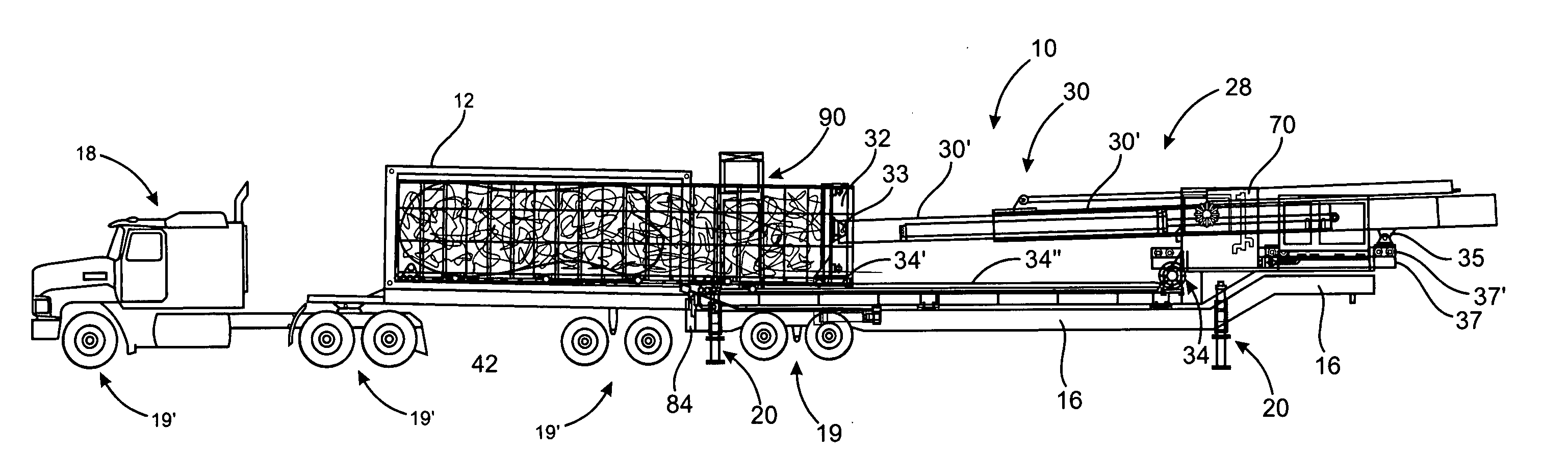
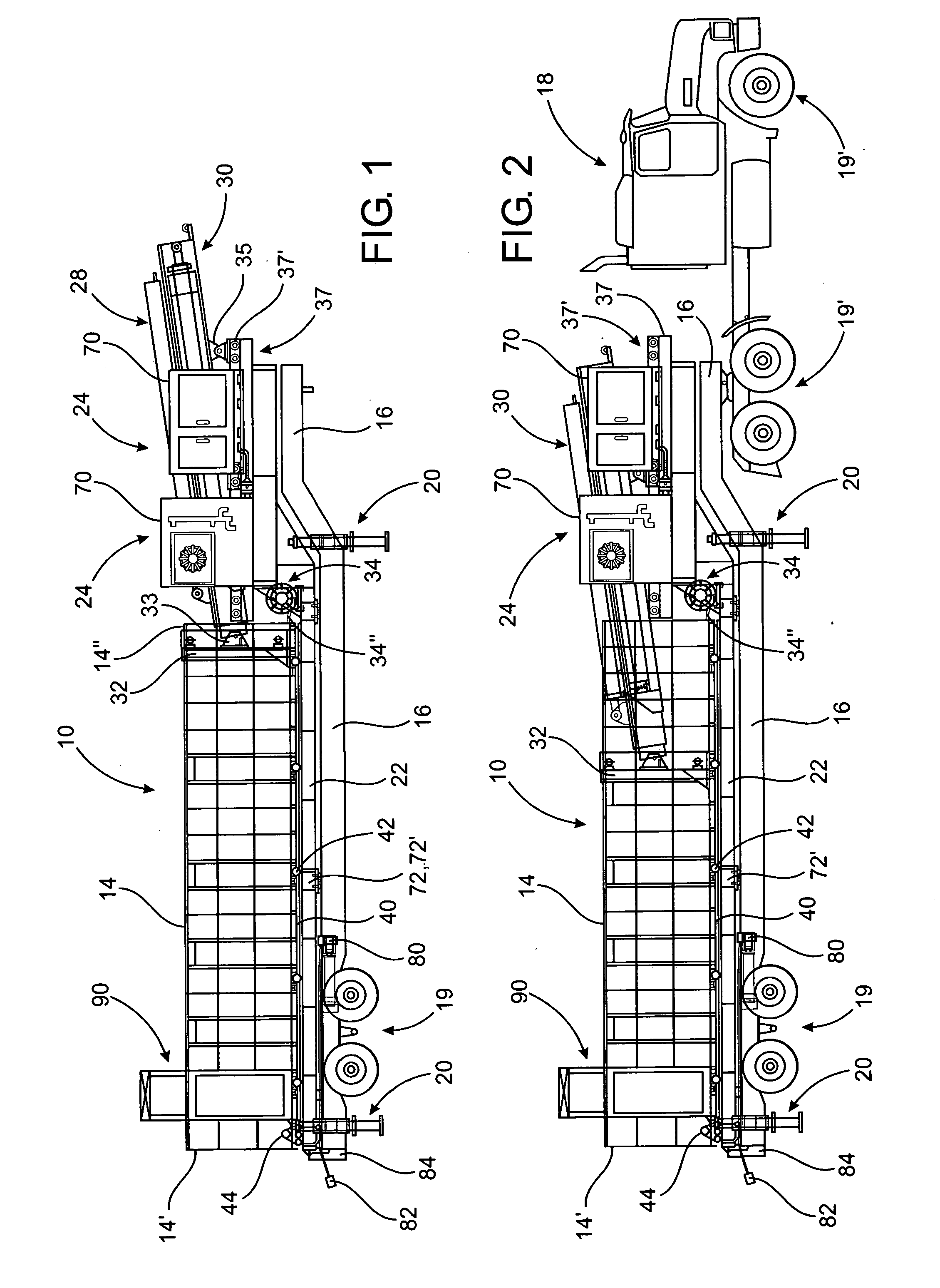
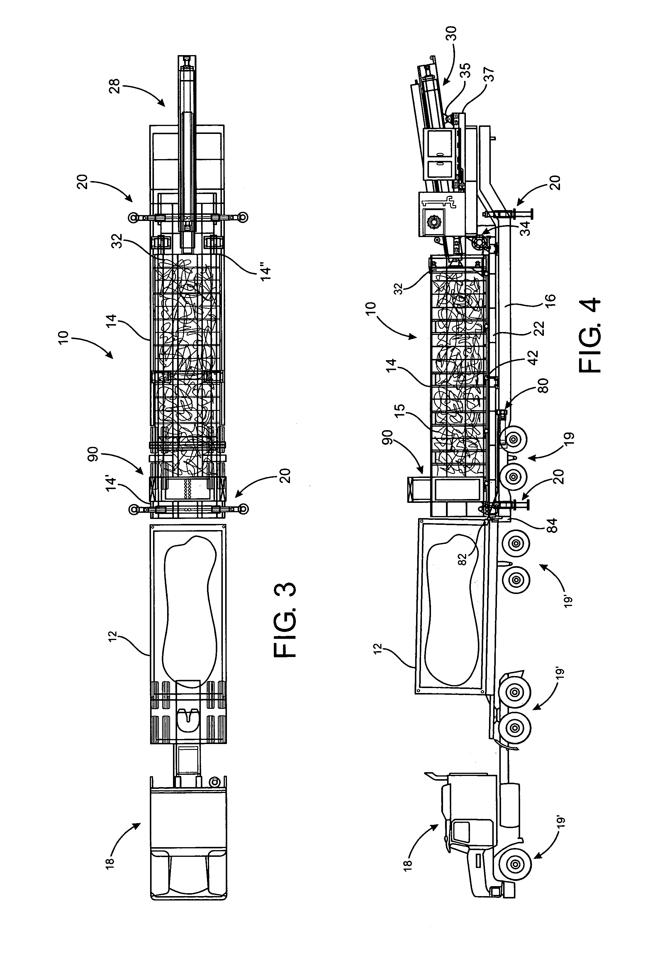
[0038]As shown in the accompanying Figures, the present invention is directed to a loading assembly, generally indicated as 10, structured for loading material into a receiving container which could take the form of a shipping or transportation container, as schematically represented as 12. While the loading assembly 10 is specifically structured for loading bulk material into the receiving container 12, a variety of other types of material can also be loaded. Accordingly, the loading assembly 10 includes a hopper generally indicated as 14 having an open top which facilitates the material 15 being deposited therein by any of a plurality of procedures and / or equipment, including those which are known in the loading industry.

[0039]Moreover, the loading assembly 10 includes a frame 16 which, as represented in FIGS. 1 and 2, may be substantially permanently disposed at a loading site as represented in FIG. 1. Alternatively, the frame 16 may at least partially define or be part of a chas...


PUM


Abstract

A loading assembly including a static or mobile frame having a platform adjustably supported thereon and a hopper for containment of material to be loaded being movable relative to the platform between a loading position and an unloading position. A positioning assembly is adjustably interconnected to the frame and cooperatively disposed and structured relative to the platform and hopper to facilitate disposition of the hopper between the loading and unloading positions. The positioning assembly is further structured to assume a retaining relation to the material initially loaded into the hopper and subsequently being unloaded from said hopper, concurrently to the movement of the hopper from the unloading position to the loading position.

Description

BACKGROUND OF THE INVENTION[0001]1. Field of the Invention[0002]This invention is directed to an assembly for loading bulk or other material into a receiving container and includes a hopper structured to facilitate collection of the material therein. The hopper is supported on and movable relative to an adjustable platform between a loading position, exteriorly of the container, and an unloading position on the interior of the container. A positioning assembly is structured to move the hopper from the loading position to the unloading position and thereafter maintain the material being loaded within the receiving container concurrently to positioning of the hopper back into the loading position on the platform.[0003]2. Description of the Related Art[0004]With the recent diversification and growth in the world steel and scrap market, suppliers have had to improvise ways to ship both type products to diverse destinations around the globe. Accordingly, shipping or transportation contai...

Claims


Application Information

Patent Timeline
IPC IPC(8): B60P1/00B65G67/26
CPCB65G67/20
Inventor LUKESIC, DARRELL LOUIS
Owner LUKESIC DARRELL LOUIS
Why Eureka
Try Eureka