Methods for self-aligned self-assembled patterning enhancement

a patterning enhancement and self-aligning technology, applied in the field of micro- or nano-scale device fabrication, can solve the problems of sup>nd /sup>pass pattern alignment inadequate, features consume time in many ways, and the resolution of the standard mask fabrication process is challenged

Inactive Publication Date: 2012-07-26
GLOBALFOUNDRIES INC
View PDF3 Cites 5 Cited by
  • Summary
  • Abstract
  • Description
  • Claims
  • Application Information

AI Technical Summary

Benefits of technology

[0006]This disclosure presents methods for producing self-aligned, self-assembled sub-ground-rule features without the need to use additional lithographic patterning. Specifically, the present disclosure allows for the creation of assist features that are localized and self-aligned to a given structure. These assist features can either have the same tone or different tone to the given feature.

Problems solved by technology

These small features challenge the resolution of the standard mask fabrication process.
If small features are desired in a different material from the main feature, 1st- to -2nd pass pattern alignment is inadequate.
These features also consume time in many ways.
The larger the data file size of the mask data, the slower the transfer of data, the slower the fracturing of the data into write-ready form, and the slower the mask fabrication process.
If a problem is found with the sub resolution feature placement or size, the entire data processing sequence must be initiated again.

Method used


Image

  • Methods for self-aligned self-assembled patterning enhancement
  • Methods for self-aligned self-assembled patterning enhancement
  • Methods for self-aligned self-assembled patterning enhancement

Examples


Embodiment Construction

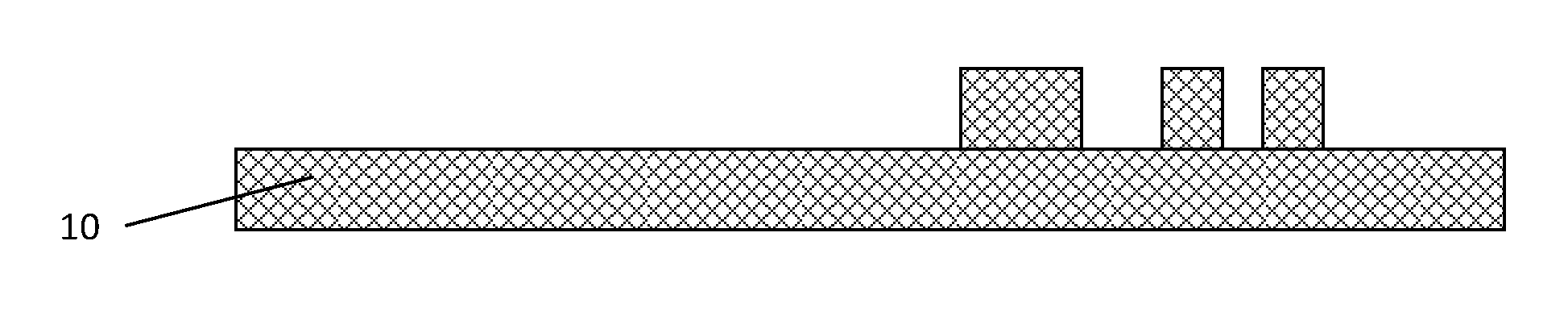
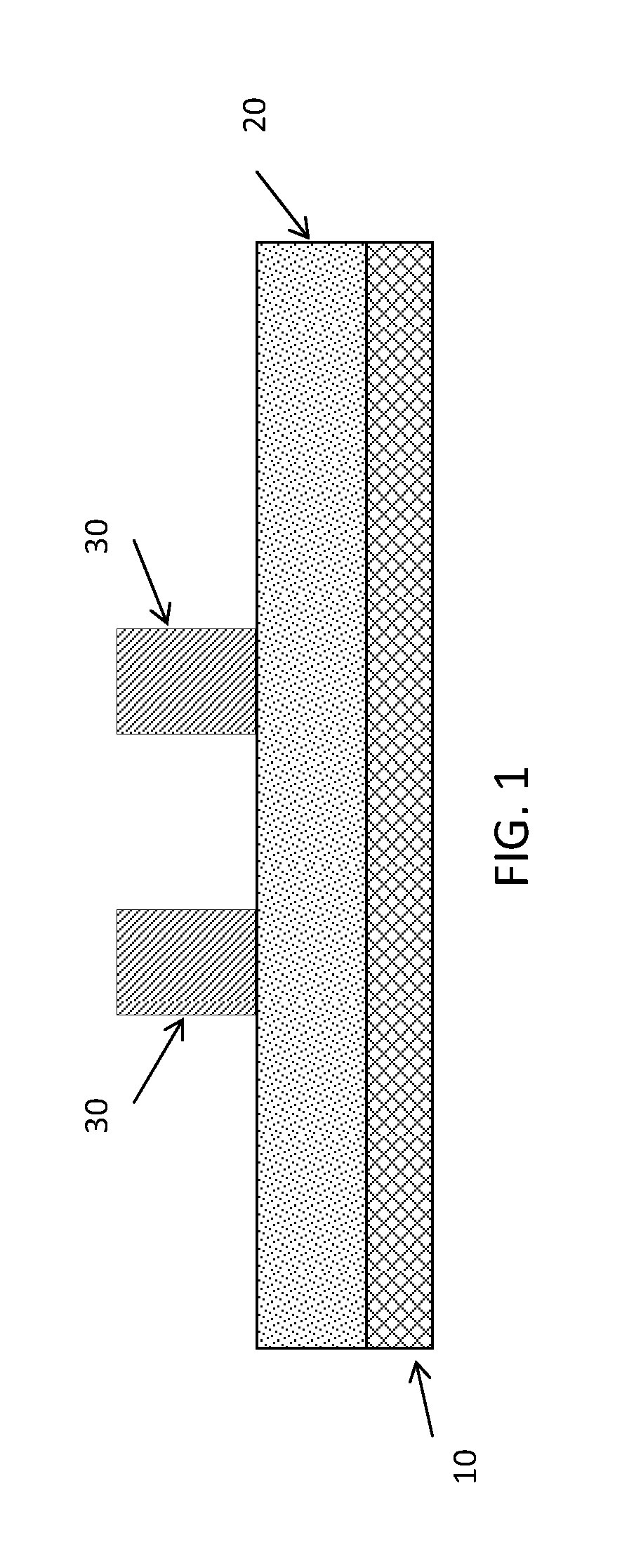
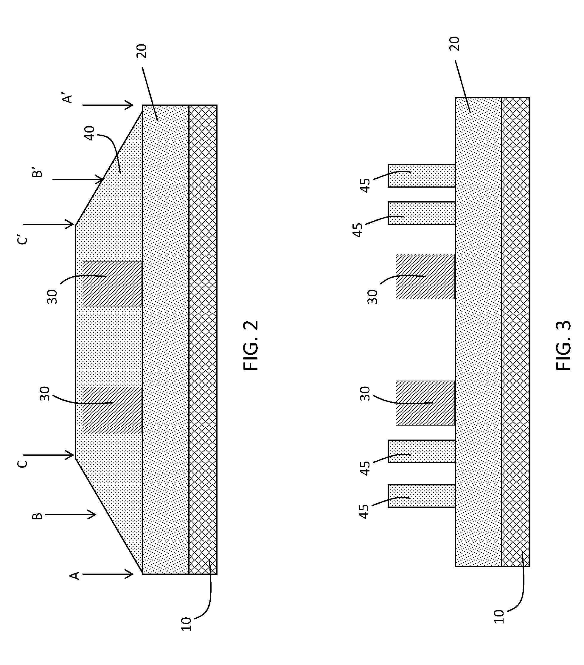
[0012]One approach in creating assist features is to begin with at least one mask patterned structure or structure 30 on top of a mask substrate 10 as shown in FIG. 1. Optionally, an image transfer material 20 may also be provided between the substrate and the patterned structures. Image transfer material 20 can be a temporary material used to transfer the pattern into mask substrate 10. Hard mask structure 30 is patterned using conventional techniques such as e-beam lithography. As demonstrated in FIG. 2, a self-assembly material 40, such as diblock copolymer, is spin coated in such a manner that the thickness of the copolymer layer varies from being thickest right next to structure 30, and being thinner as the distance away from the feature is increased. The spin speed and viscosity of the diblock is chosen so that the diblock thickness is in the right range for self-assembly to occur only between regions B and C, and B′ and C′, as show in FIG. 2. For sections between regions A an...


PUM


Abstract

Methods for producing self-aligned, self-assembled sub-ground-rule features without the need to use additional lithographic patterning. Specifically, the present disclosure allows for the creation of assist features that are localized and self-aligned to a given structure. These assist features can either have the same tone or different tone to the given feature.

Description

BACKGROUND OF THE INVENTION[0001]1. Technical Field[0002]The invention relates generally to micro-scale or nano-scale device fabrication, and more particularly, to methods for forming a mask with self-aligned, self-assembled sub-lithographic features.[0003]2. Background Art[0004]A mask is a glass or quartz plate containing information about the features to be printed on a semiconductor wafer. This information is contained in variations in the plate that create differences in topography, transmittance or phase. The mask is used as a master template to transfer design images onto a wafer either through exposure to radiation (lithography) or through direct contact (nanoimprint). The mask is an intermediate step created to transfer the design to the wafer image, so the mask features are adjusted to create the desired wafer image.[0005]A simple form of altering the mask data is to change the size or shape of the mask feature so that the printed wafer feature size matches the desired feat...

Claims


Application Information

Patent Timeline
Patent Type & Authority Applications(United States)
IPC IPC(8): H01L21/31
CPCB81C1/00031B81C2201/0149B81C2201/0198G03F1/36G03F7/0002
Inventor CLEVENGER, LARRYDALTON, TIMOTHY J.RADENS, CARL J.
Owner GLOBALFOUNDRIES INC
Why Eureka
Try Eureka