Reusable Medical Device with Advanced Counting Capability

Inactive Publication Date: 2012-07-26
TYCO HEALTHCARE GRP LP
View PDF12 Cites 225 Cited by
  • Summary
  • Abstract
  • Description
  • Claims
  • Application Information

AI Technical Summary

Benefits of technology

[0016]The present disclosure also describes a limited use disposable end effector assembly including a shaft with a proximal end and a distal end, an actuating jaw mechanism connected to the distal end of the shaft that delivers electrosurgical energy received from the shaft to tissue, a control circuit disposed in the shaft between the electrosurgical instrument housing assembly and the actuating jaw mechanism and an indicator. The proximal end of the shaft is configured to selectively attached to a distal end of an electrosurgical instrument housing assembly and is configured to selectively receive electrosurgical energy from the electrosurgical instrument housing assembly. The control circuit is selectively actuatable to enable the flow of electrosurgical energy to and from the actuating jaw mechanism. The indicator is coupled to the shaft and configured to indicate a parameter related to the use of the limited use disposable end effector assembly. The control circuit prevents activation of the actuating jaw mechanism when the parameter indicates the useful life of the limited use disposable end effector assembly has expired.
[0017]The present disclosure also describes an electrosurgical system that

Problems solved by technology

A limited use reusable instrument includes instruments with a limited useful life, wherein the useful life of the instrument may be based the number of electrical activations, the cumulative time of electrical activation, the number of mechanical activations, the number of surgical procedures performed or any combination thereof.
In some instances there may be a temptation to re-use disposable instruments or u

Method used


Image

  • Reusable Medical Device with Advanced Counting Capability
  • Reusable Medical Device with Advanced Counting Capability
  • Reusable Medical Device with Advanced Counting Capability

Examples


Example

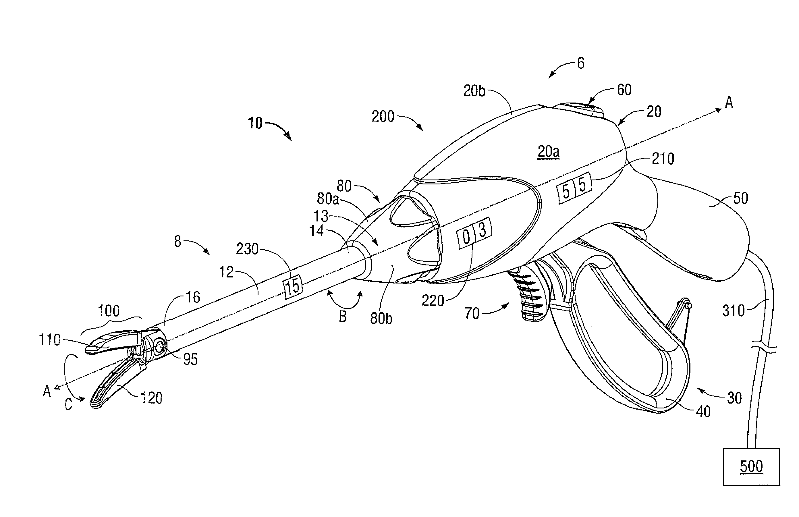
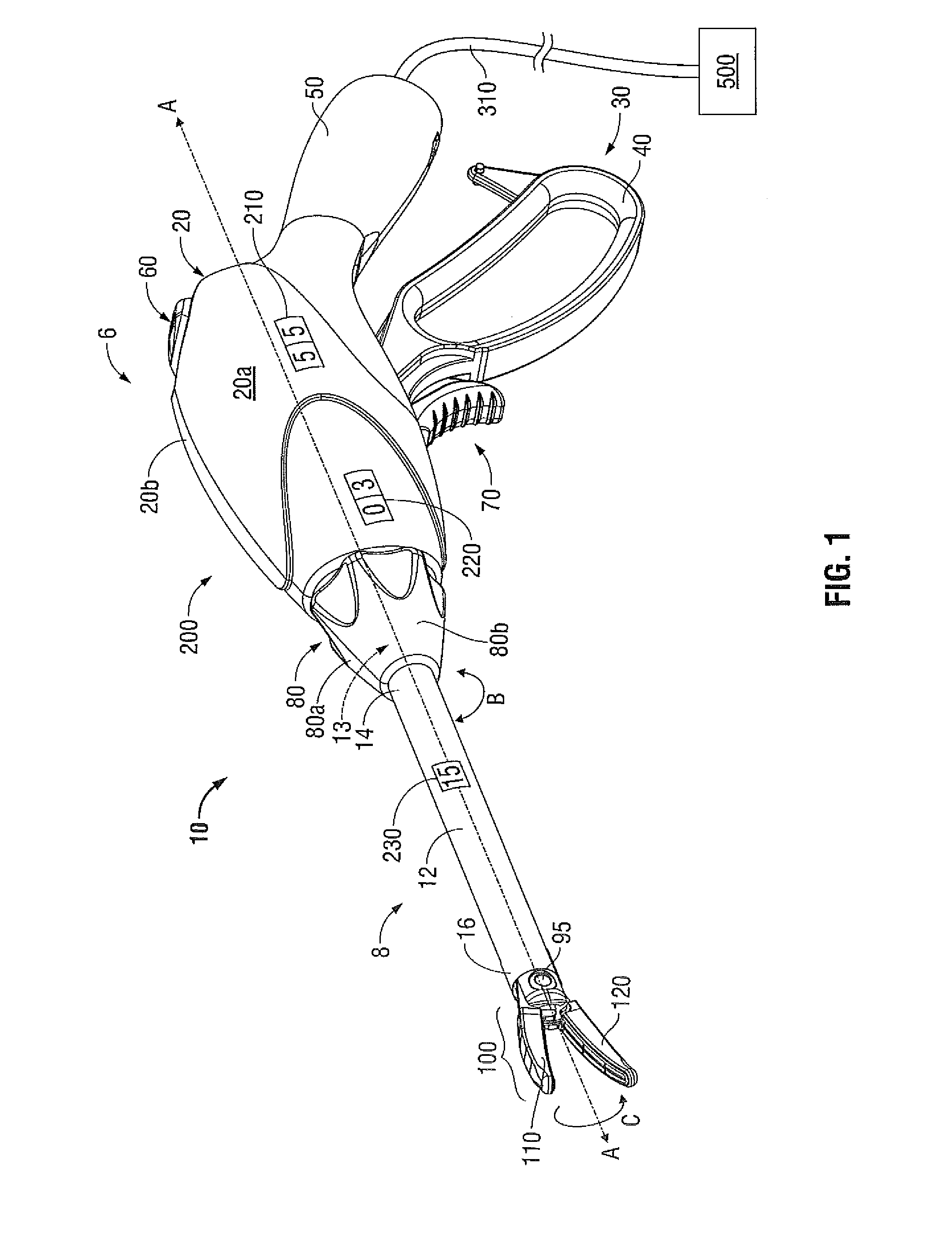
[0034]In the drawings and in the descriptions which follow, the term “proximal,” as is traditional, will refer to the portion of the instrument closer to the user, while the term “distal” will refer to the end of the instrument farther from the user.

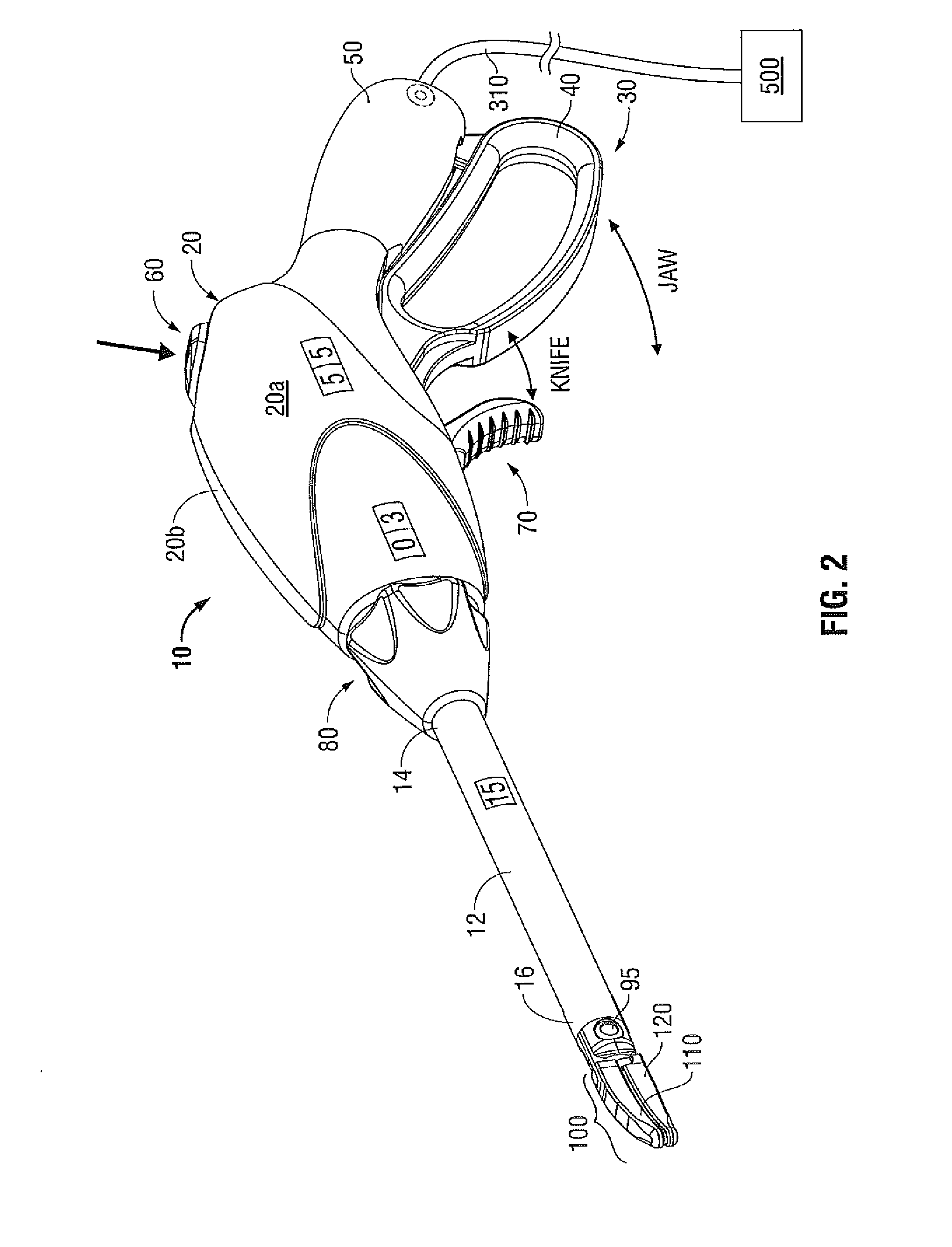
[0035]Turning now to FIGS. 1 and 2, one embodiment of a bipolar forceps 10 (i.e., forceps 10) is shown for use with various surgical procedures and generally includes a housing assembly 6, a shaft and end effector assembly 8 and a use indicator system 200. The housing assembly 6 and the shaft and end effector assembly 8 mutually cooperate to grasp, seal and divide large tubular vessels and large vascular tissues. The use indicator system 200 is integrated into the housing assembly 6 and / or the shaft and end effector assembly 8 and includes control circuitry 205 (see FIG. 3) and one or more use indicators 210, 220, 230. Control circuitry 205 is configured enable and / or disable the delivery of electrosurgical energy based on the use of the...


PUM


Abstract

An electrosurgical instrument including a housing assembly having a first disposable treatment portion selectively attached thereto. The disposable treatment portion is adapted to connect to an electrosurgical generator that supplies energy to the electrosurgical instrument. A control circuit is included and disposed in electrical communication between the electrosurgical generator and the first disposable treatment portion. The control circuit is selectively actuatable to enable the flow of electrosurgical energy from the electrosurgical generator to the first disposable treatment portion. An indicator, coupled to the housing assembly or the first disposable treatment portion, is configured to indicate a parameter related to the use of the electrosurgical instrument. The control circuit is configured to prevent activation of the electrosurgical instrument when the parameter of the indicator indicates the useful life of the disposable treatment portion has expired.

Description

BACKGROUND[0001]1. Technical Field[0002]The present disclosure relates to a limited use reusable electrosurgical instrument and more particularly, the present disclosure relates to systems and methods for tracking and controlling the use of electrosurgical instruments and reusable portions thereof.[0003]2. Background of Related Art[0004]The use of electrosurgical instruments is well known in the art. Electrosurgical instruments typically utilize both mechanical clamping action and electrical energy to affect hemostasis by heating the tissue and blood vessels to coagulate, cauterize and / or seal tissue. Over the course of a surgical procedures a clinician may use a variety of electrosurgical instruments such as, for example, elongated electrosurgical forceps to cauterize, coagulate / desiccate and / or to simply reduce or slow bleeding in a surgical cavity, electrosurgical pencil or scalpel for cutting or to cauterize a surgical opening, an electrosurgical vessel sealing device including ...

Claims


Application Information

Patent Timeline
IPC IPC(8): A61B18/04A61B17/28
CPCA61B18/1206A61B18/1445A61B18/1477A61B2018/00577A61B2018/00589A61B2019/4831A61B2018/0063A61B2018/1412A61B2018/1495A61B2019/4815A61B2018/00595A61B2090/0803A61B2090/0806
Inventor ALLEN, CHARLES D.
Owner TYCO HEALTHCARE GRP LP
Why Eureka
Try Eureka