
Armrest structure for vehicle and setting method of armrest height for vehicle

a technology of armrest height and vehicle, which is applied in the direction of roofs, chairs, doors, etc., can solve the problems of passenger discomfort and inappropriate feelings

Active Publication Date: 2012-08-02
MAZDA MOTOR CORP
View PDF2 Cites 0 Cited by
  • Summary
  • Abstract
  • Description
  • Claims
  • Application Information

AI Technical Summary

Benefits of technology

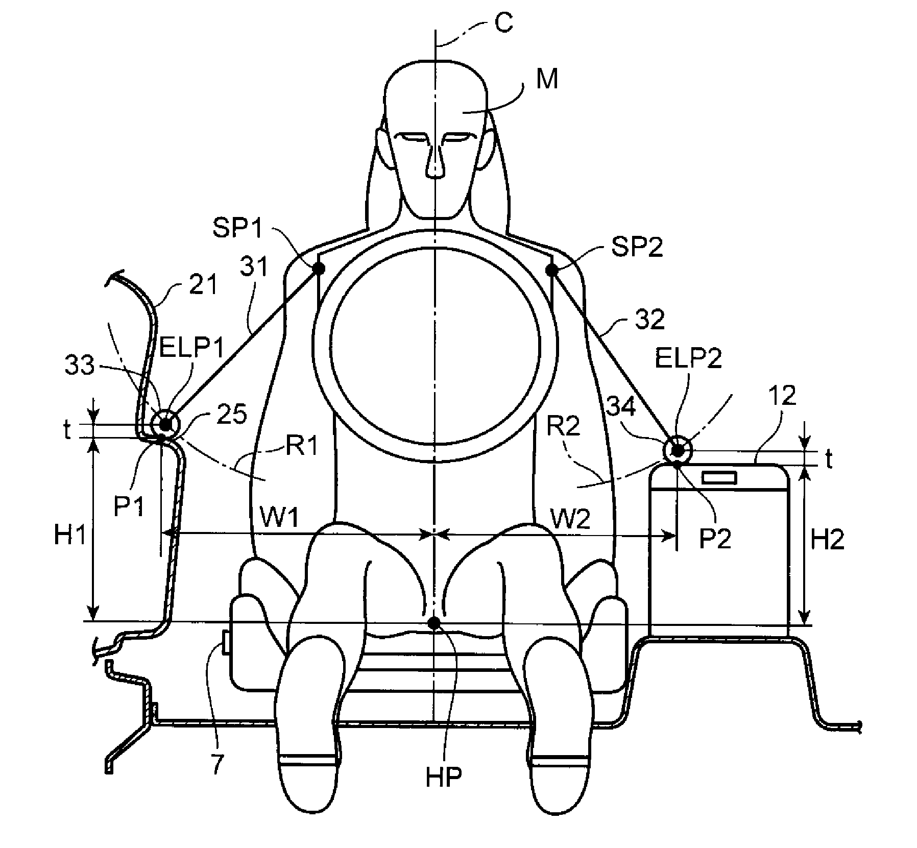
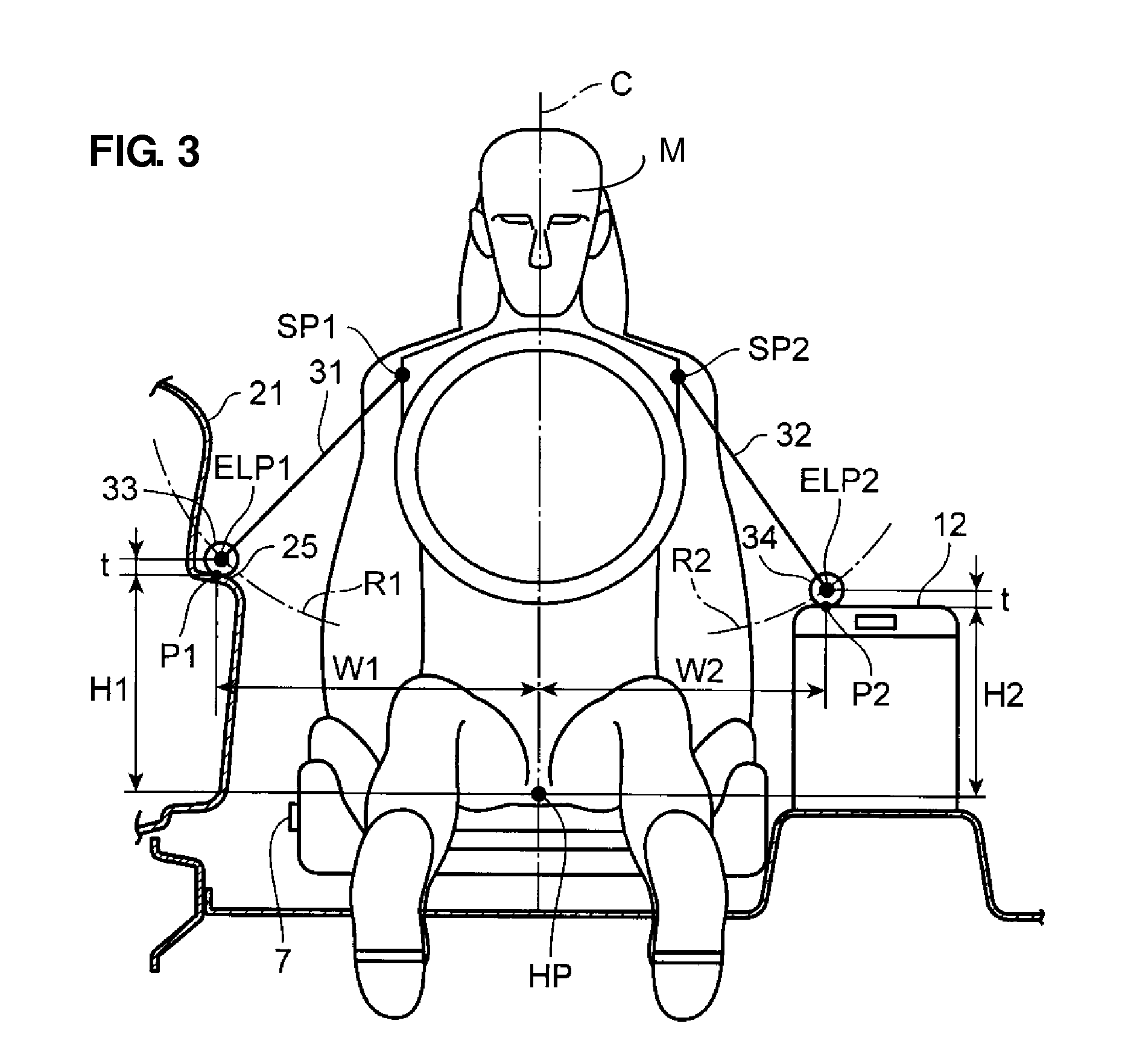
[0009]According to the present invention, since it is set such that the height of the first armrest having the greater (longer) horizontal distance from the vertically-extending seat center line is greater (higher) than that of the second armrest having the smaller (shorter) horizontal distance from the vertically-extending seat center line, an appropriate difference in the height between the first and second armrests can be provided in accordance with an increase of the armrest height when an outward angle of the upper arm portion of the seated passenger opens widely. Accordingly, the passenger's elbows can be properly supported at the first and second armrests regardless of the difference in the horizontal distance between the first armrest and the second armrest. Thereby, even when the passenger places the elbow on any of the first and second armrests, the appropriate elbow's support feelings can be ensured for the passenger and the passenger can obtain a more comfortable position.
[0010]According to an embodiment of the present invention, a height of each of the elbow's support positions at the first and second armrests is set at a level corresponding to a locus of a rotational motion of an upper arm portion of the arm of the passenger seated in the seat, the locus of the rotational motion of the upper arm portion of the passenger's arm being formed by the elbow when the upper arm portion of the passenger's arm rotates, in a vehicle width direction, around a shoulder position of the passenger seated in the seat. Thereby, the height of each of the first and second armrests can be set properly in accordance with the locus of the rotational motion of the passenger's upper arm portion, so that the appropriate elbow's support feelings at the first and second armrests can be ensured more properly.
[0014]According to another embodiment of the present invention, an operational portion for seat-position adjustment is provided at a side face of the seat which is located on the one side of the seat in the seat width direction where the first armrest is provided, and the second armrest is located on the other side of the seat which is opposite to the operational portion for seat-position adjustment. Thereby, a necessary space for the passenger operating the operational portion for seat-position adjustment with a hand can be provided properly, ensuring the appropriate elbow's support feelings at the first and second armrests.
[0016]According to another embodiment of the present invention, at least one of the first and second armrests is configured such that the height thereof is changeable within a specified adjustable range and a highest position in the specified adjustable range corresponds to the elbow's support position located on the locus of the rotational motion of the upper arm portion of the passenger seated in the seat. Thereby, in a case in which the height of at least one of the first and second armrests is changeable, the height of the armrest can be easily adjusted to an appropriate position to support the passenger's elbow by the passenger raising the armrest up to the highest position, and when the armrest is not used, the armrest can be properly lowered so as not to hinder the passenger in his / her driving.

Problems solved by technology

Accordingly, even though the armrest height is changeable, there is a concern that in a case in which the position of the armrest in a vehicle width direction is extremely close to or far away from the seat, for example, the appropriate elbow's support feelings may not be provided to the passenger.
In particular, in a case in which armrests are provided on right and left sides of the seat (on both sides in the vehicle width direction), any difference in elbow's support feelings between the right side and the left side may cause some uncomfortable (inappropriate) feelings to the passenger.

Method used


Image

  • Armrest structure for vehicle and setting method of armrest height for vehicle
  • Armrest structure for vehicle and setting method of armrest height for vehicle
  • Armrest structure for vehicle and setting method of armrest height for vehicle

Examples


Embodiment Construction

[0024]Hereafter, a preferred embodiment of the present invention will be described referring to the accompanying drawings.

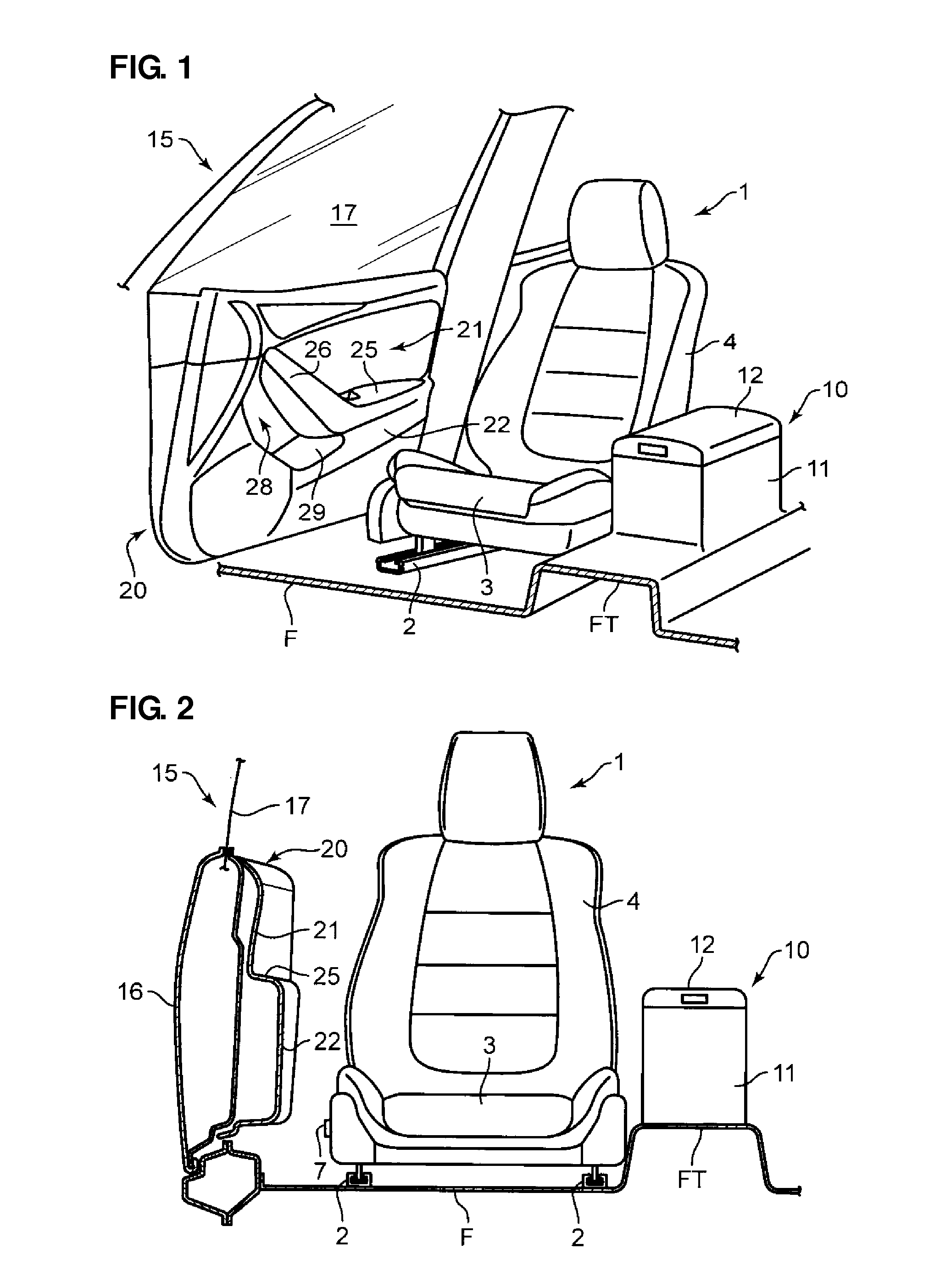
[0025]FIGS. 1 and 2 show a state of a vehicle compartment of a vehicle equipped with an armrest structure according to an embodiment of the present invention. As shown in FIGS. 1 and 2, a driver's seat 1 (hereinafter, referred to as a seat 1 simply) in which a passenger (driver) driving the vehicle is seated is provided on a floor F of the vehicle compartment.

[0026]The seat 1 comprises a seat cushion 3 which is supported to slide longitudinally on the floor F via a pair of seat slide rails 2, and a seatback 4 which is provided to rise upwardly from a rear end portion of the seat cushion 3. The seatback 4 is pivotally supported at the seat cushion 3 via a reclining mechanism, not illustrated, so that a rearward-inclined angle of the seatback 4 is changeable within a specified range in accordance with an operation of the reclining mechanism.

[0027]An operational por...


PUM


Abstract

An armrest structure for a vehicle of the present invention comprises a first armrest to support an elbow of one of arms of a passenger seated in a seat and a second armrest to support an elbow of the other arm of the passenger. A horizontal distance W1 between a vertically-extending seat center line of the seat and an elbow's support position at the first armrest is greater than a horizontal distance W2 between the vertically-extending seat center line and an elbow's support position at the second armrest, and a height H1 of the elbow's support position at the first armrest is greater than a height H2 of the elbow's support position at the second armrest. Accordingly, the passenger's elbows can be properly supported at the armrests on both sides, in a seat width direction, of the seat.

Description

BACKGROUND OF THE INVENTION[0001]The present invention relates to an armrest structure for a vehicle and a setting method of an armrest height for a vehicle, which comprises a first armrest to support an elbow of one of arms of a passenger seated in a seat, the first armrest being provided on one side of the seat in a seat width direction, and a second armrest to support an elbow of the other arm of the passenger seated in the seat, the second armrest being provided on the other side of the seat in the seat width direction.[0002]Conventionally, as disclosed in Japanese Patent Laid-Open Publication No. 2010-221843, a structure, in which a lid to open or close an upper face of a console box provided in a vehicle is used as an armrest and a height of the console box (the height of the armrest at the upper face of the console box) is changeable by using a spring to raise or lower the console box and a positioning mechanism to hold the console box at a specified height, is known.[0003]Ac...

Claims


Application Information

Patent Timeline
Patent Type & Authority Applications(United States)
IPC IPC(8): B60N2/46B60N2/75
CPCB60N2/466B60N2/464B60N2/78B60N2/77
Inventor OHTSUBO, TOMONORIHIRASHIMA, ISAOYATSUSHIRO, YOJI
Owner MAZDA MOTOR CORP
Learn More