Autofocusing eyewear, especially for presbyopia correction

a technology for presbyopia and eyewear, applied in the field of presbyopia correction, can solve the problems of loss of orientation, cumbersome approach, and person's inability to accommodate their eyes by

Inactive Publication Date: 2012-08-02
LIGHT PRESCRIPTIONS INNOVATORS
View PDF5 Cites 177 Cited by
  • Summary
  • Abstract
  • Description
  • Claims
  • Application Information

AI Technical Summary

Benefits of technology

[0011]One aspect of the present invention is related to presbyopia correcting autofocusing eyewear, and to an eye parallax tracker and a variable focus lens suitable for use in such eyewear. The eyewear comprises a controller, an integrated eye parallax tracker and a variable focus eyeglass lens connected in a closed loop system. Unlike prior art gaze tracking systems (that use either the First or Fourth Purkinje imaging points, Ref. [2], or the First Purkinje point and imaging of the limbus, Ref. [1]), which are bulky, embodiments of the present eyewear use images of the First Purkinje point for both eyes to allow a lightweight and compact system.

Problems solved by technology

However, by the age of 50 the average person can only accommodate their eyes by 2 diopters, a ten to one reduction.
Such an approach is cumbersome, especially when the user has both hands busy, such as in a driving situation.
However, basing the switch of prescription on moving one's head downward may be appropriate for reading but inappropriate for many other common situations.
For example, in the case where someone is walking down a staircase, looking downward, the refocusing of glasses might result in a loss of orientation and potentially incurring an injury.
These techniques are too cumbersome for the typical user of the proposed autofocusing eyewear.
The presence of such attachments would be uncomfortable and severely limit the number of uses of the eyewear.
In addition, when the eye changes its direction of gaze, the limbus image is severely deformed and sophisticated post processing is required to determine the direction of gaze based on the image.
This post processing would result in a delay in the response of the eyewear and also the system would likely be plagued by low accuracy.
Unfortunately, contemporary cornea / pupil reflection measurement devices are bulky and cannot be efficiently integrated into the autofocusing eyewear.

Method used


Image

  • Autofocusing eyewear, especially for presbyopia correction
  • Autofocusing eyewear, especially for presbyopia correction
  • Autofocusing eyewear, especially for presbyopia correction

Examples


Embodiment Construction

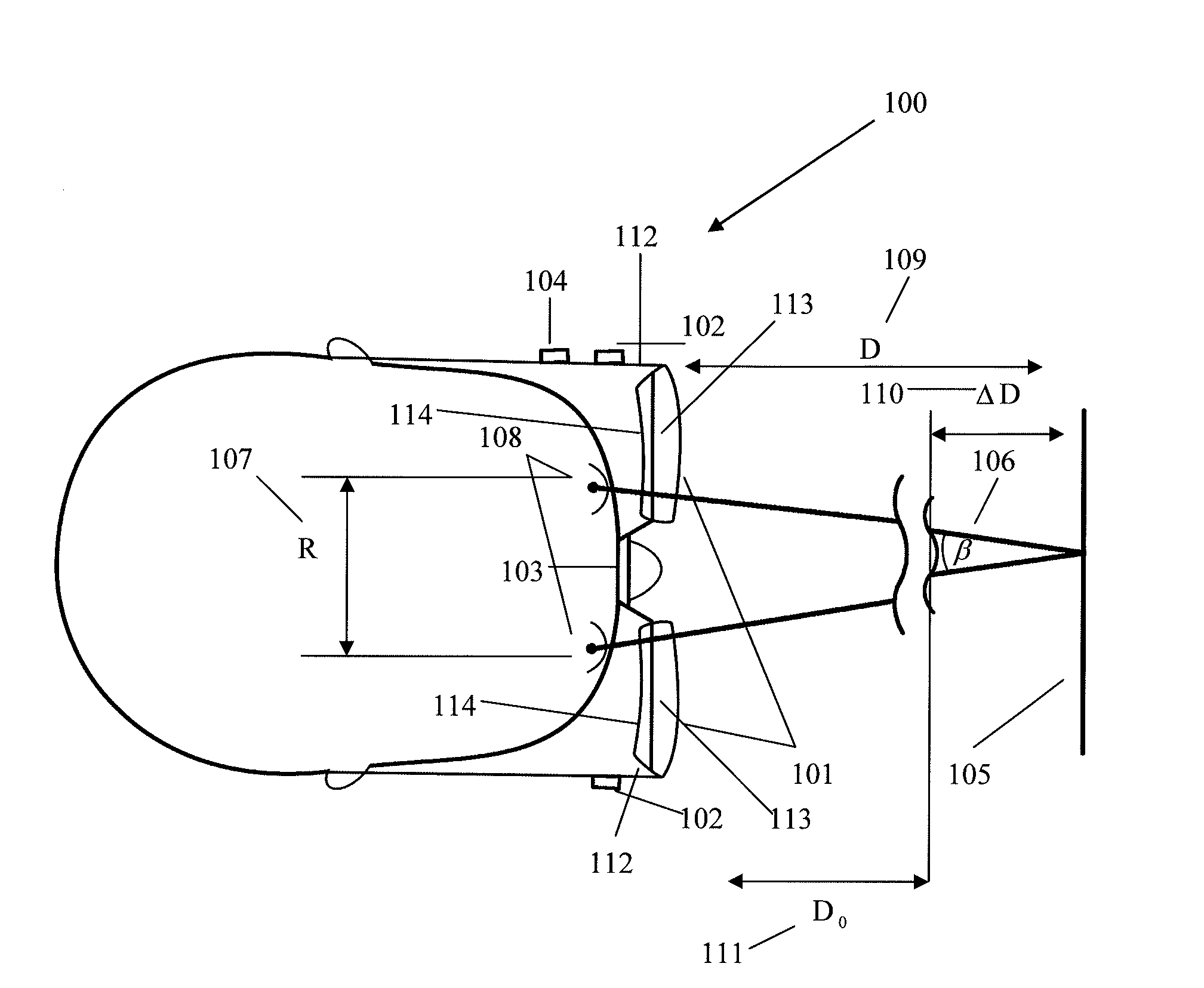
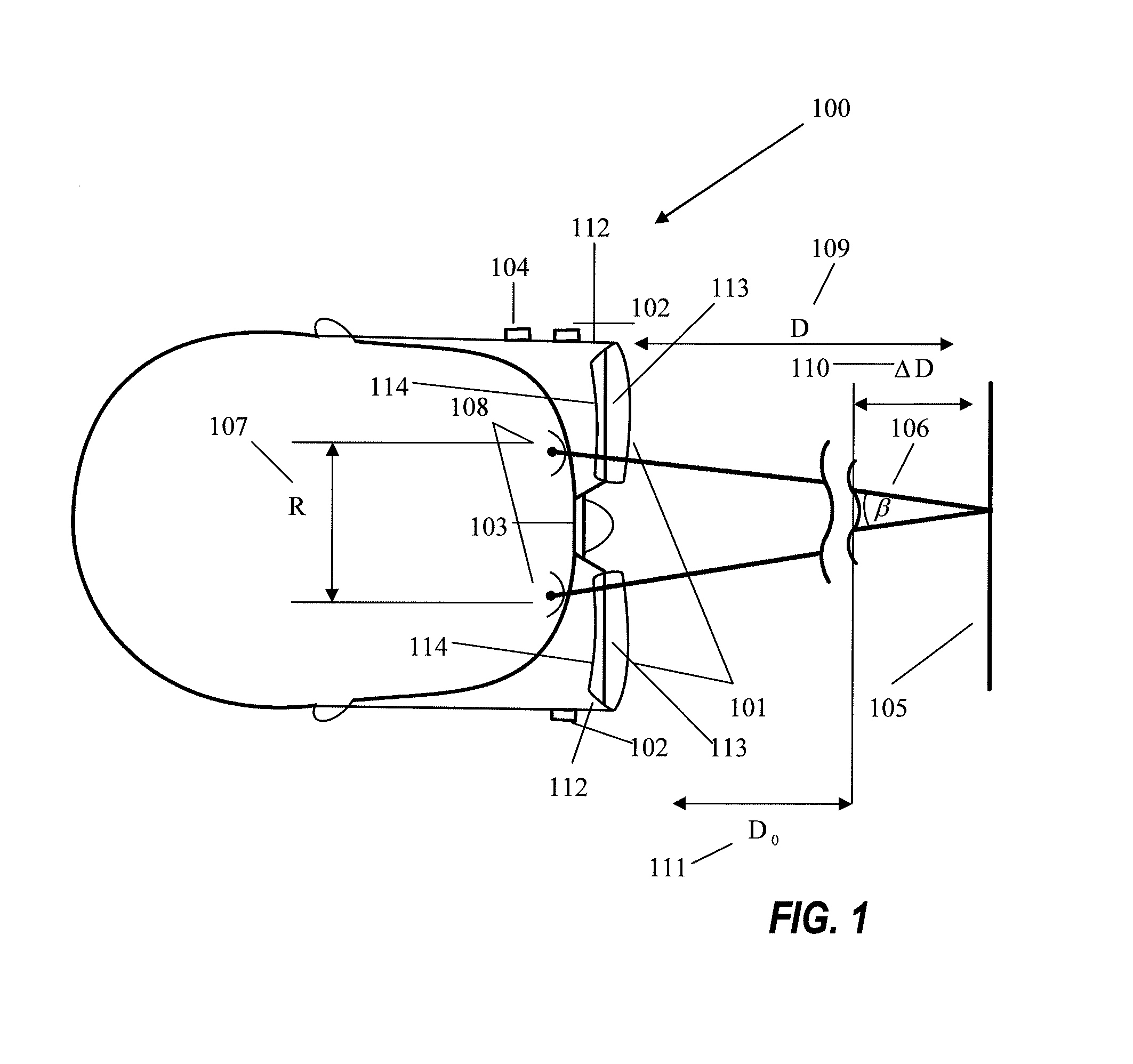
[0032]FIG. 1 is a schematic diagram that illustrates the functionality of an embodiment of autofocusing presbyopia correcting eyewear, indicated generally by reference numeral 100. In eyewear 100 there are two eyeglass optics 101, each comprising a variable power lens 113 and a gaze tracker waveguide 114. The gaze tracker waveguide 114 has a volume reflection hologram for redirecting a gaze tracker illumination beam from waveguide to the eye as well as redirecting cornea reflex back to the waveguide. Also in FIG. 1 is eye parallax tracker electronics 102. The eye parallax tracker has a cornea illumination system, a cornea reflex imager and a controller 104. The autofocusing eyewear described herein has a variable focus lens driver 103 and a system controller 104. An object plane 105 is at distance 109 (D). When the user concentrates his or her gaze on an object in object plane 105, the lines of gaze for the left and right eyes define parallax angle β106 and distance R 107 between co...


PUM


Abstract

A pair of eyewear has transparent waveguides in each eyewear lens. An illumination subsystem directs a beam of light through the waveguides onto a wearer's eyes. A First Purkinje point imaging subsystem for each lens uses light reflected from the eyes through the waveguides. A controller calculates from the positions of the First Purkinje points the wearer's gaze parallax angle and/or the distance to an object of interest on which the gaze of the wearer's eyes converges. The output of the controller may drive variable-focus eyeglass lenses to enable a presbyopic wearer to focus on the object. Modified Alvarez variable-focus lenses are described.

Description

CROSS REFERENCE TO RELATED APPLICATIONS[0001]This application claims benefit of U.S. Provisional Patent Application No. 61 / 437,183, filed Jan. 28, 2011 by Agurok, and of U.S. Provisional Patent Application No. 61 / 627,213, filed Oct. 7, 2011 by Agurok, both of which applications are incorporated herein by reference in their entirety.[0002]This application makes reference to U.S. Pat. No. 3,305,294, issued Feb. 21, 1967 to Alvarez, which is incorporated herein by reference in its entirety.BACKGROUND OF THE INVENTION[0003]Presbyopia is a condition where the eye has diminished ability to focus on near objects, a so-called reduction in the ability of the eye to “accommodate” (change the shape of the lens). Usually presbyopia progressively gets worse after a certain age of an individual, typically starting after the age of 40. Young children nearly all have the ability to focus their eyes from infinity down to as close as a distance of 50 mm, after correction for any far or near sight (20...

Claims


Application Information

Patent Timeline
Patent Type & Authority Applications(United States)
IPC IPC(8): G02C7/08A61B3/113
CPCG02C7/081A61B3/113
Inventor AGUROK, ILYA
Owner LIGHT PRESCRIPTIONS INNOVATORS
Why Eureka
Try Eureka