Combined Stimulation with Controlled Light Distribution for Electro-Optical Cochlear Implants

Inactive Publication Date: 2012-08-02
MED EL ELEKTROMEDIZINISCHE GERAETE GMBH
View PDF33 Cites 41 Cited by
  • Summary
  • Abstract
  • Description
  • Claims
  • Application Information

AI Technical Summary

Problems solved by technology

One challenge associated with optical stimulation is to control the shape and direction of the light field, particularly in view of the variation in rotational orientation of the light source carrier inside the cochlea.

Method used


Image

  • Combined Stimulation with Controlled Light Distribution for Electro-Optical Cochlear Implants
  • Combined Stimulation with Controlled Light Distribution for Electro-Optical Cochlear Implants
  • Combined Stimulation with Controlled Light Distribution for Electro-Optical Cochlear Implants

Examples


Embodiment Construction

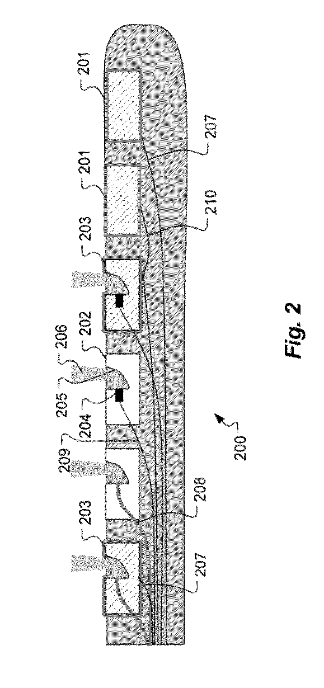
[0018]Various embodiments of the present invention are directed to an implantable stimulation device which includes an implantable stimulation source carrier for insertion into or adjacent to target tissue. The stimulation source carrier includes stimulation contacts for delivering neural stimulation signals to nearby target tissue. At least one of the stimulation contacts is an electromagnetic radiation stimulation element having multiple individual electromagnetic radiation stimulation sub-elements for delivering electromagnetic stimulation signals to the nearby target tissue. The electromagnetic radiation stimulation element may optionally include at least one electrical stimulation sub-element for delivering electrical stimulation signals to the nearby target tissue. In the following description, the specific embodiments described use light signals and optical stimulation elements as the specific form of electromagnetic radiation, but it is to be understood that electromagnetic ...


PUM


Abstract

An implantable stimulation device is described which includes an implantable stimulation source carrier for insertion into or adjacent to target tissue. The stimulation source carrier includes stimulation contacts for delivering neural stimulation signals to nearby target tissue. At least one of the stimulation contacts is an optical stimulation element having multiple individual optical stimulation sub-elements for delivering optical stimulation signals to the nearby target tissue with controlled shape and direction.

Description

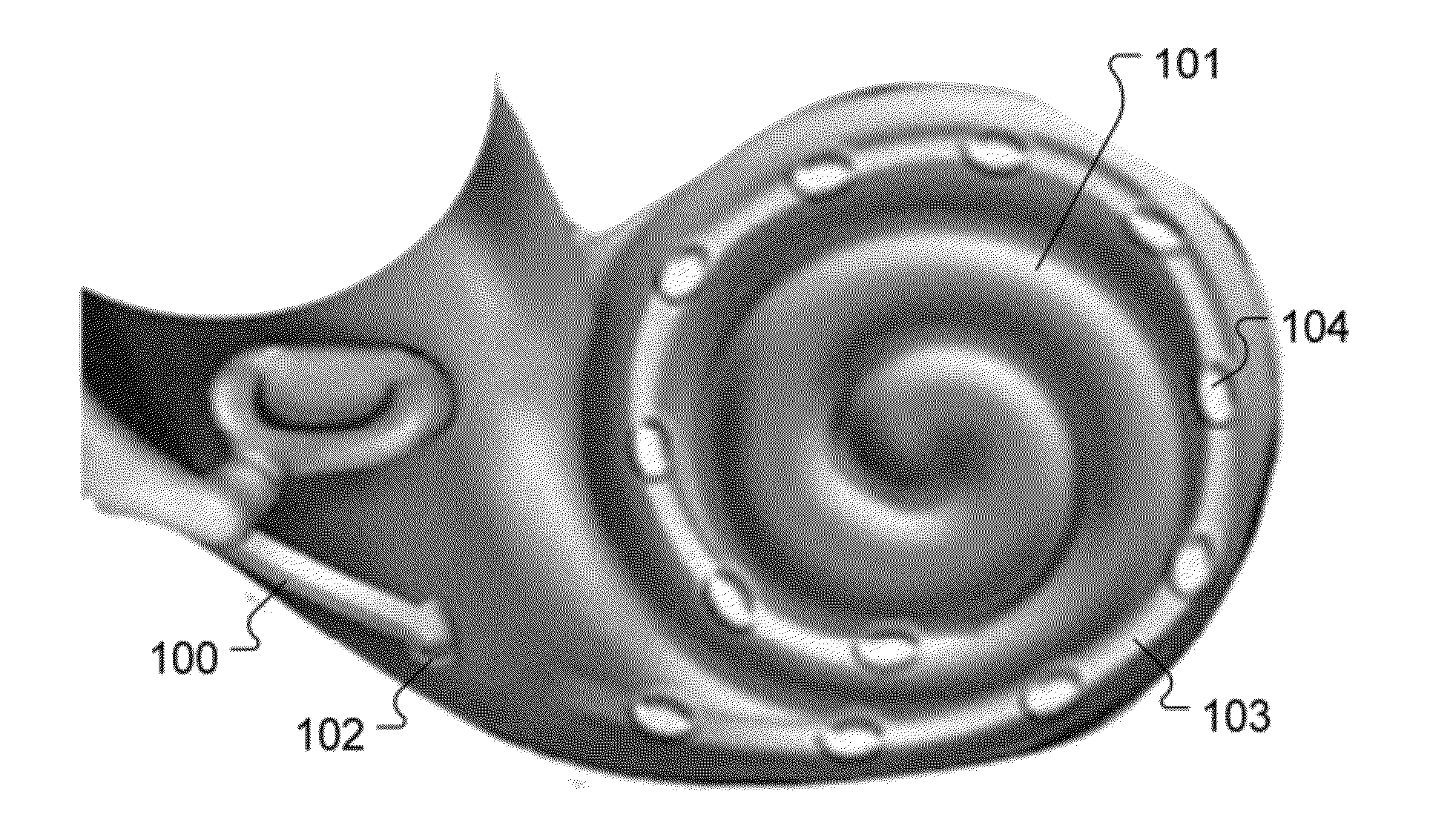
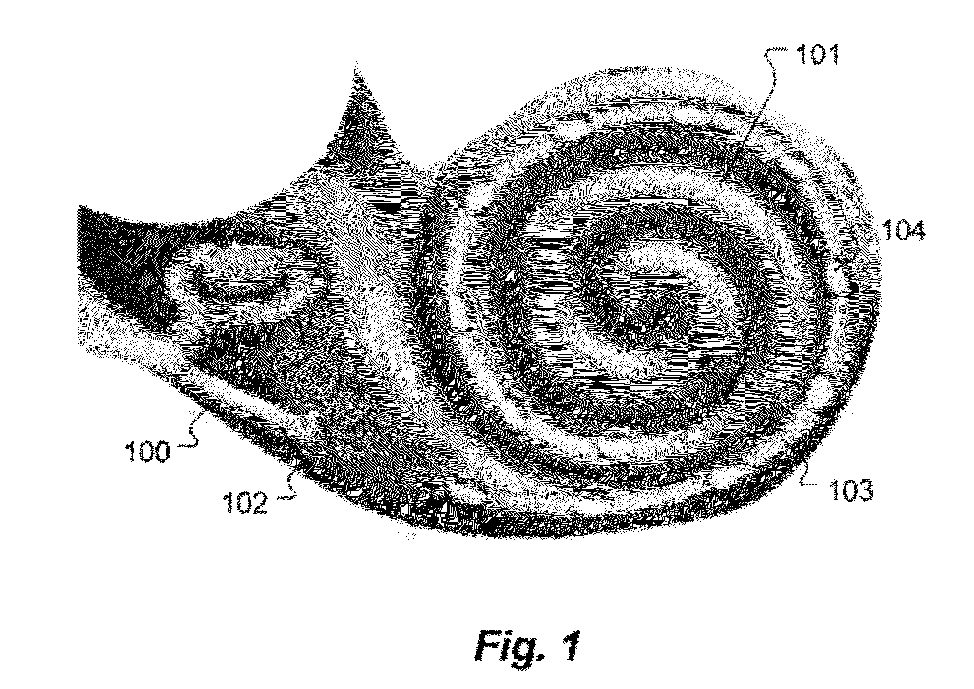
[0001]This application claims priority from U.S. Provisional Patent 61 / 436,823, filed Jan. 27, 2011, which is incorporated herein by reference.TECHNICAL FIELD[0002]The present invention relates to stimulation signals used in neural implant devices such as cochlear implants.BACKGROUND ART[0003]Neural implant systems such as cochlear implants deliver stimulation signals to target neural tissue. For example, FIG. 1 shows a cochlear implant arrangement where an implant electrode 100 penetrates through a cochleostomy opening 102 into a patient cochlea 101. The intra-cochlear portion of the implant lead is referred to as the electrode array 103 and includes multiple stimulation contacts 104 that deliver electrical stimulation signals to auditory neural tissue within the cochlea 101.[0004]Existing commercial neural implant systems are based on the use of electrical stimulation signals, but there have been some recent proposals to stimulate nerves either optically or optically in combinatio...

Claims


Application Information

Patent Timeline
Patent Type & Authority Applications(United States)
IPC IPC(8): A61F11/04A61N1/05
CPCA61N1/0541A61N5/0601A61N5/0603A61N5/0622A61N2005/0605A61N2005/067A61N2005/0631A61N2005/0647A61N2005/0652A61N2005/0665A61N2005/0666A61N2005/063A61N5/067
Inventor VOGT, GERHARDGARNHAM, CAROLYN
Owner MED EL ELEKTROMEDIZINISCHE GERAETE GMBH
Why Eureka
Try Eureka