Optical stimulation of photosensitized cells

a technology of photosensitized cells and optical stimulation, which is applied in the field of optical stimulation of light sensitized cells, can solve the problems of limited stimulation spatial resolution, possible electrical excitation of action potentials, and potential excitation of neurons within the vicinity of the stimulation electrode, etc., and achieves maximum efficacy, easy bonding, and increased fill factor

Inactive Publication Date: 2011-06-02
IMPERIAL INNOVATIONS LTD
View PDF8 Cites 24 Cited by
  • Summary
  • Abstract
  • Description
  • Claims
  • Application Information

AI Technical Summary

Benefits of technology

[0014]The optical system may comprise at least one imaging component arranged to form an image of the light sources at the sample position. The optical system may be arranged to cause convergence of the light from the light sources onto an area at the sample which is smaller then the light source array. This can be advantageous, for example because stimulation of cells in specific localities can improve the kinetics of stimulation.
[0016]The control means may be arranged to control each of the light sources independently. For example the control means may be arranged to control at least one of: the intensity, the frequency of illumination pulses, and the duration of illumination pulses of the light sources. In some cases pulsing of the light from each of the light sources is required, and in some embodiments the pulse length, or the pulse period, is arranged to be less than 1 ms. Our experiments show that reducing pulse width can in some cases improve the kinetics of the photosensitized cells, improve their long term survival, and reduce the overall power consumption of the system.
[0025]In one aspect, the invention provides a device for multi-site stimulation of biological cells or tissues based on light. It may be designed to work with existing recording techniques, such as patch clamp electrophysiology, extracellular recording such as microelectrodes array, cellular calcium imaging, or other fluorescently linked metabolic imaging methods. The system may consist of an array of miniature light sources such as light-emitting-diodes (LED)s that is imaged on to the sample. It may have optics for integrating the micro-light sources into a microscope or incubator. The stimulating pattern (amplitude, pulse width and repetition rate, wavelength) of each stimulating spot may be independently tuneable in real time. The actual position of the light dot array can be easily finely tuned in the focal plane by moving the platform with the sample on the microscope. The invention can also provide a method for a closed-loop control where the responses of the cells are fed back to the system and used to tune the stimulating light pattern, a method to determine the photon flux per cell, a method for calibration and a method to cool the micro-light sources for higher efficiency.
[0029]If the light source comes from a LED's or VCSEL's array, the individual emitters will generally have spacing between them. Thus it can be advantageous to incorporate micro-optical components such as micro-lenses to increase the fill factor. As a result the light sources, e.g. LED's, can be arranged into both square matrix and hexagonal arrays to achieve maximum efficacy. In the case of GaN LEDs, which are presently the optimum light source, the substrate can be transparent, so it is possible to emit from either the top or bottom side. Bottom side emission allows for the top side to be easily bonded to CMOS controller chips. Additionally the layering of the substrate results in some natural diffusion of the light emitted from the LED sources.System Optics
[0030]The optics of the described invention can facilitate the incorporation of one or more light emissive sources. The use of beam splitters and / or wavelength dependent mirrors can facilitate the addition of multiple light sources to be overlaid over each other. Additionally, lenses may be used to manipulate the light beams from the light emissive arrays, and to focus the combined beams on the sample. In the case of the epi- version of this invention, a modification may be carried out on the microscope filter whereby the output barrier filter is removed from its normal position and a new filtering component is incorporated nearer the camera. As such it is therefore advantageous to combine any image recording system such as a digital camera within this described method.Opto-Mechanics

Problems solved by technology

The stimulation spatial resolution is limited by propagation of the electrical pulse through the solution and thus all the neurons within the vicinity of the stimulation electrode are potentially excited.
Finally, it is only possible to electrically excite action potentials, not inhibit them.
However, the photo-stimulation concept is not actually new.
Presently, while it is conceivable to chemically induce photosensitivity into existing membrane receptors, no such system exists without genetic manipulation.
2008), but have not fully presented how a fully functional system may be comprised.
For many reasons these approaches are not optimal.

Method used


Image

  • Optical stimulation of photosensitized cells
  • Optical stimulation of photosensitized cells
  • Optical stimulation of photosensitized cells

Examples


example

Photo-Stimulation of Neurons

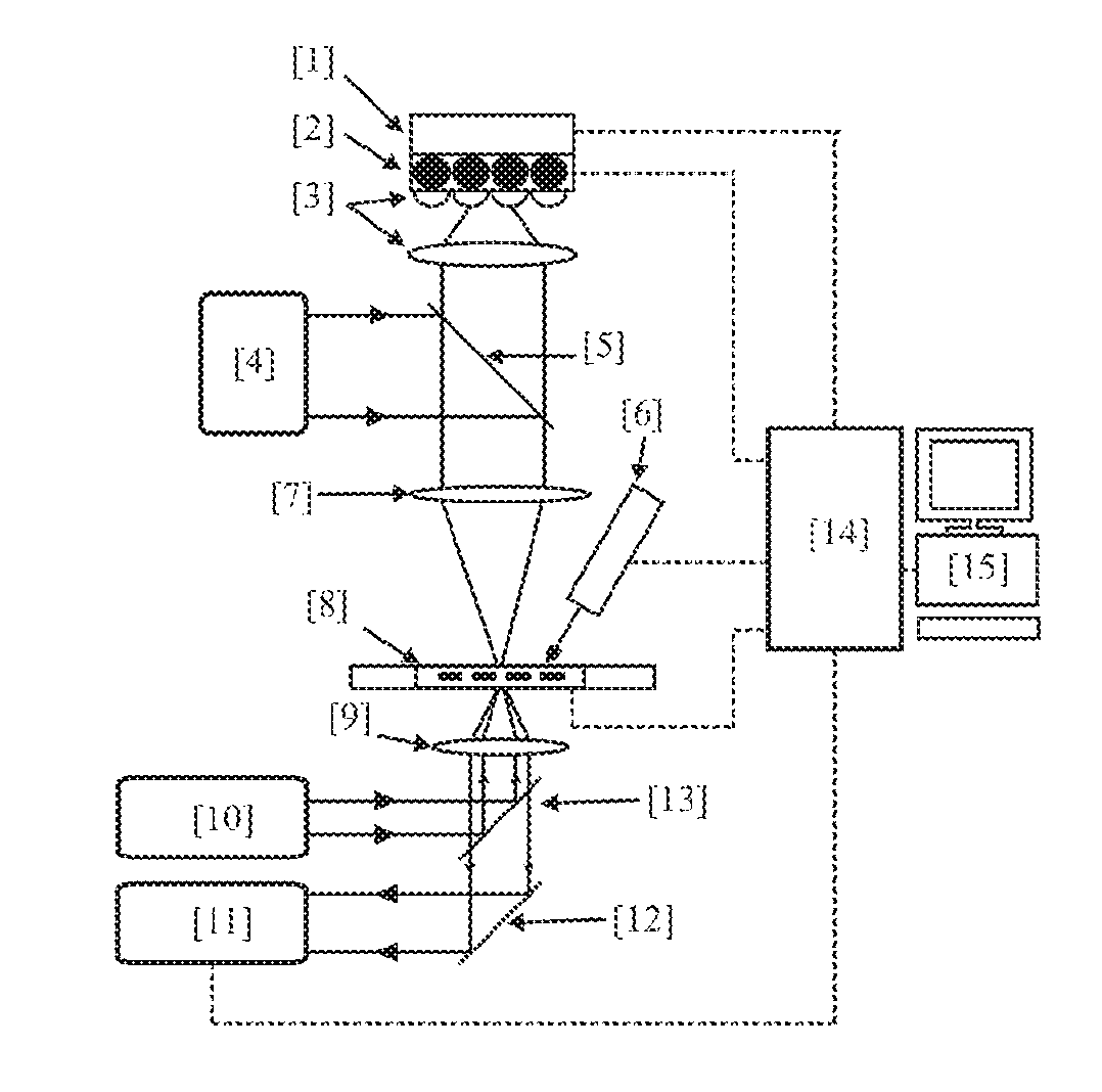
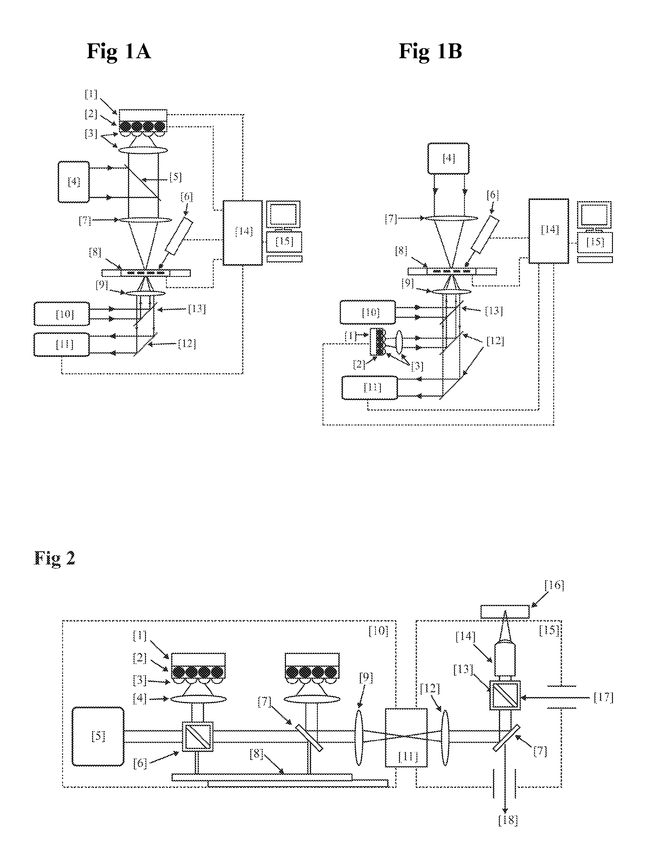
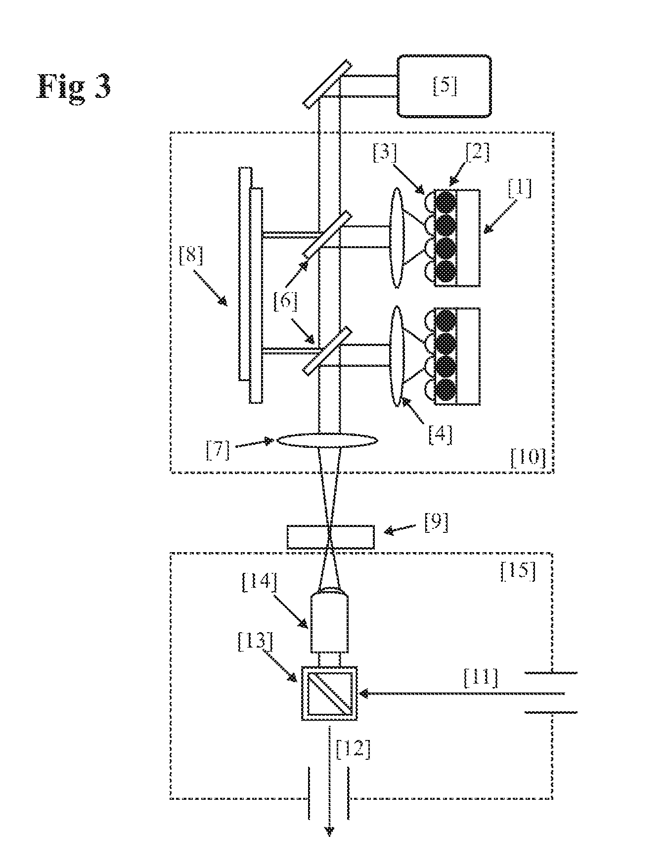
[0068]In order to use micro-LED array devices for photo-stimulation and simultaneous electrical recording of nerve cells the system shown schematically in FIG. 1 can be used. The system is constructed around an inverted microscope for sample imaging and alignment. The MEA system is mounted on the stage of this microscope and the photo-stimulation is provided by mounting the LED array and projection optics in a trans-illumination position above the stage. Ancillary electronics including LED driver and MEA instrumentation are controlled by a computer, which can adjust the stimulation and record the nerve cell response as required. Commercially available MEA recording systems typically consist of a matrix of Indium Tin Oxide electrodes on a glass substrate, coated with Titanium Nitride at the stimulation / recording points. Non-stimulating areas are passivated with silicon nitride. The array is thus fairly transparent to both trans-illuminated and epi-illumina...


PUM


Abstract

This invention describes a device for optical stimulation of cells and other biological structures. It has an ability to target multiple cells and / or multiple sub-cellular targets. The stimulation optical pattern on each cell can be independently controlled with individual frequencies. The light sensitivity of the cells can be imparted as a result of genetic expression of surface and / or subsurface proteins, chemical modification of existing proteins, or via the release of caged entities which in turn act to stimulate the cell through chemical means. The embodiment is capable of functioning on neurons but can also be used for other cells. It can perform optimal stimulation with sub-cellular resolutions, record the activity of the targeted cells and perform processing to ensure calibration.

Description

FIELD OF INVENTION[0001]This invention relates to methods and apparatus to optically stimulate light sensitized cells.BACKGROUND TO THE INVENTION[0002]Over the years we have gained considerable insight into the functioning of neurons since the original discoveries in 1952. Patch clamping has been an effective tool to investigate the biochemical factors involved in neural signalling. More recently the emergence of multi-electrode array (MEA) technology has provided researchers with multi site recording and even stimulation capabilities. MEA technology is used today extensively to study the dynamic of interactions within neuron networks, synaptic plasticity visual perception and effects of pharmacological compounds and putative therapeutics.[0003]Although an MEA provides a good recording means and has advantages over patch clamp in that multiple stimulation and recording sites are accessible, MEA's suffer from major drawbacks. There is a short dead time between the stimulation pulse a...

Claims


Application Information

Patent Timeline
Patent Type & Authority Applications(United States)
IPC IPC(8): G01J1/16A61N5/06G02B21/06
CPCG01N21/6458G02B21/0032G02B21/16G02B21/0076G02B21/004
Inventor GROSSMAN, NIRDEGENAAR, PATRICKNIKOLIC, KONSTANTINNEIL, MARKKENNEDY, GORDONPOHER, VINCENT
Owner IMPERIAL INNOVATIONS LTD
Why Eureka
Try Eureka