High pressure mechanical safety valve

a safety valve and high pressure technology, applied in the direction of check valves, valve details, functional valve types, etc., can solve the problems of pulsing loads or high, achieving and not being suitable for a forced closure of the valv

Inactive Publication Date: 2012-08-09
GEA MECHANICAL EQUIP ITAL
View PDF7 Cites 15 Cited by
  • Summary
  • Abstract
  • Description
  • Claims
  • Application Information

AI Technical Summary

Benefits of technology

[0011]to ensure that the device i

Problems solved by technology

However it cannot achieve a forced closure of the valve, it is not suitable in the case of pulsing loads and it relates to low temperatures and not to high temperatures.
DE 43056

Method used


Image

  • High pressure mechanical safety valve
  • High pressure mechanical safety valve
  • High pressure mechanical safety valve

Examples


Embodiment Construction

.

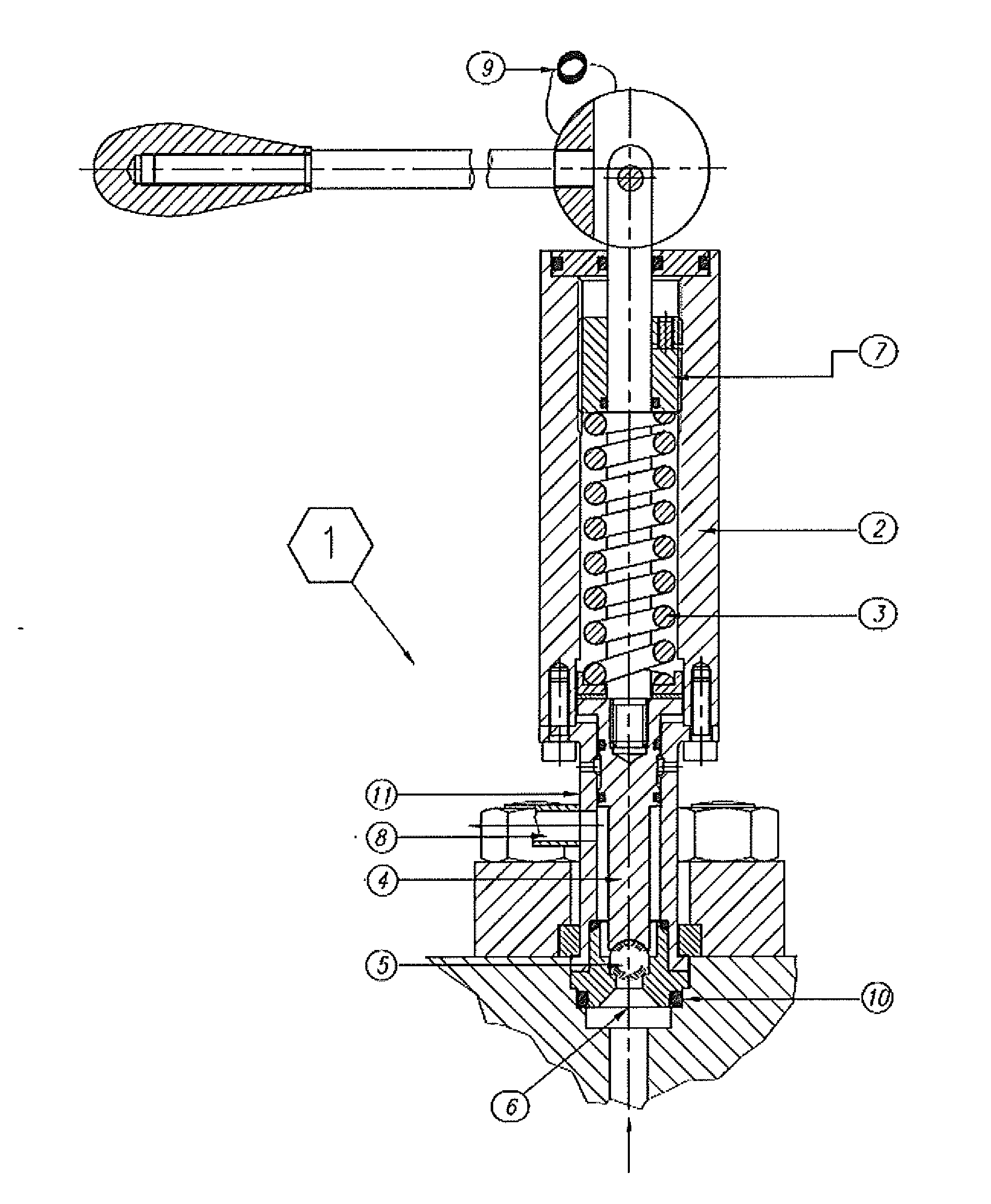
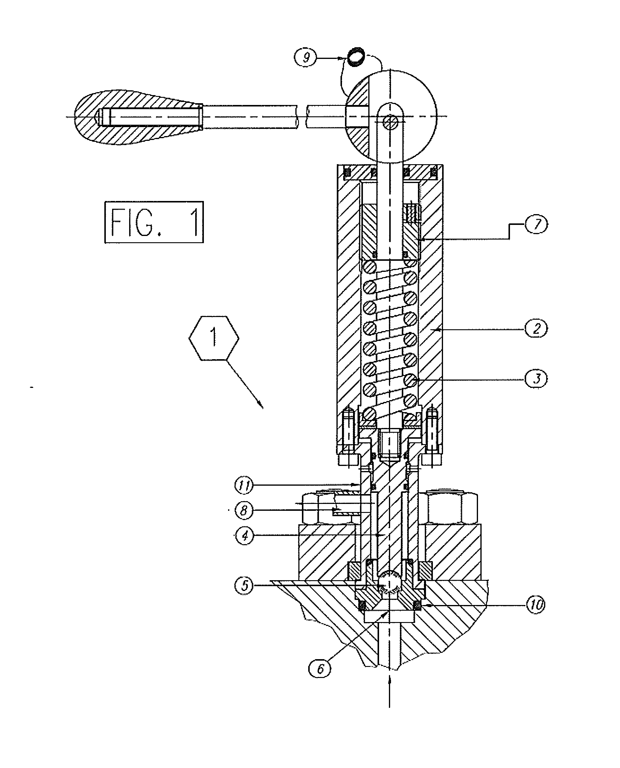
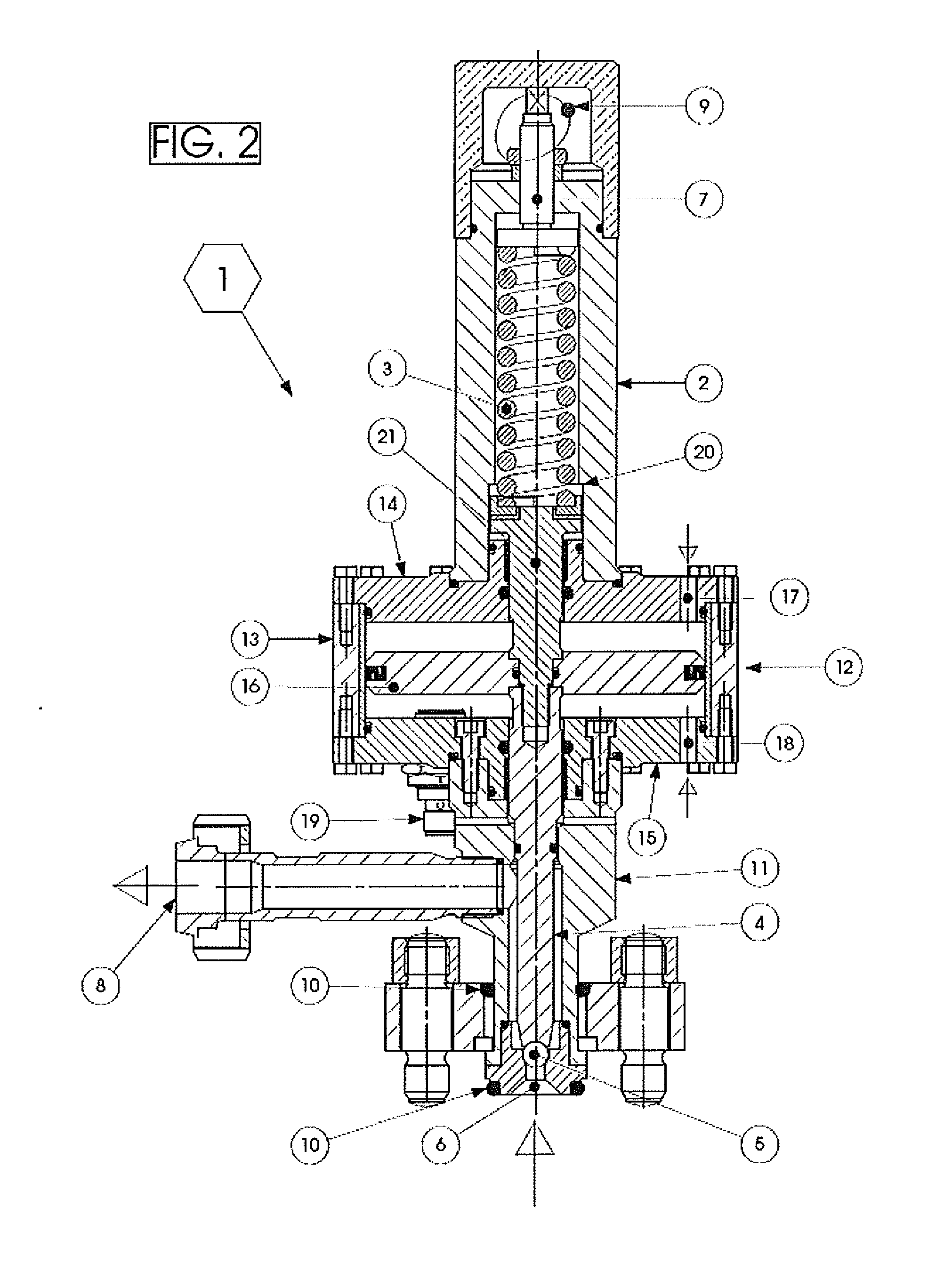
[0021]With reference to the figures, 1 indicates overall an overpressure valve, normally installed on the compression head of a homogenizer or on the high-pressure delivery line of a pump to protect the machine and the operators from accidental overpressures.

[0022]The valve 1 has a body 2 in which there is inserted a spring 3 acting upon the stem of a shutter element 4 ending with a free sphere 5, preferably of the ceramic type, suitable for closing an aperture 6 in contact with high pressure environments.

[0023]Unlike the flat or conical shutter elements of the previously mentioned prior art, which are not suitable for high pressures or pulsing loads, the free sphere 5 allows operation with pulsing loads present in the lower high pressure area. There are also present longitudinal guides (absent in the aforementioned prior art) which allow operation with pulsing loads.

[0024]The sphere 5 is thus maintained in a closed position by means of the load of the spring 3, whereas it moves in...


PUM


Abstract

A high pressure mechanical safety valve (1), of the type comprising a body (2) housing elastic means (3) acting on a shutter element (4) normally maintained in a closing position when the pressure in a high pressure area beyond an aperture (6) is lower than the pressure, settable to a fixed calibration value, exerted by the elastic means (3). The safety valve comprises mechanical means for remote control of the valve, interposed between the elastic means (3) and the shutter element (4) to allow both a forced opening or a forced closing of the valve (1) The safety valve may also comprise an optional position sensor for signalling the open or closed status of the valve.

Description

TECHNICAL FIELD AND BACKGROUND ART[0001]The present invention relates to a mechanical safety valve for environments with high / very high pressures (up to 2200 bar) and high temperatures, applicable to a wide range of flow rates (30-60000 l / h); it has prevalent use in high pressure pumps and homogenizers, which must be equipped with safety devices that prevent them from reaching critical conditions that imply risks of sudden breaks and a hazard for users.[0002]The presence of an overpressure or pressure limiting valve for protection against possible overpressures that may be created inside the compression head as a result of the pumping action of the machine to which to valve is applied is already known.[0003]Said valve, schematically illustrated in FIG. 1, comprises a spring for releasing overpressures and also an opening lever mounted on an eccentric for manually deactivating the preload and hence the valve on the occasion of equipment flushing cycles (CIP) to clean the seat of the ...

Claims


Application Information

Patent Timeline
IPC IPC(8): F16K21/04
CPCF16K31/122F16K17/0486Y10T137/7837
Inventor GIOBERTI, FABIOMADURERI, MICHELE
Owner GEA MECHANICAL EQUIP ITAL
Why Eureka
Try Eureka