
Rotating wheel electronic display apparatus

a technology of electronic display and rotating wheel, which is applied in the field of rotating wheel electronic display apparatus, can solve the problems of limiting the size and complexity of the display it is capable of producing, requiring high rotation rate to produce a quality display, and its large single-piece circuit board is comparatively very expensive to manufacture, and achieves the effect of convenient installation

Active Publication Date: 2012-08-09
PIKE BRANDS LLC
View PDF5 Cites 28 Cited by
  • Summary
  • Abstract
  • Description
  • Claims
  • Application Information

AI Technical Summary

Benefits of technology

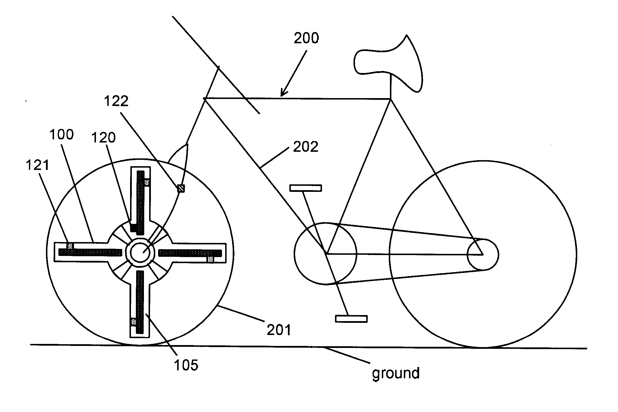
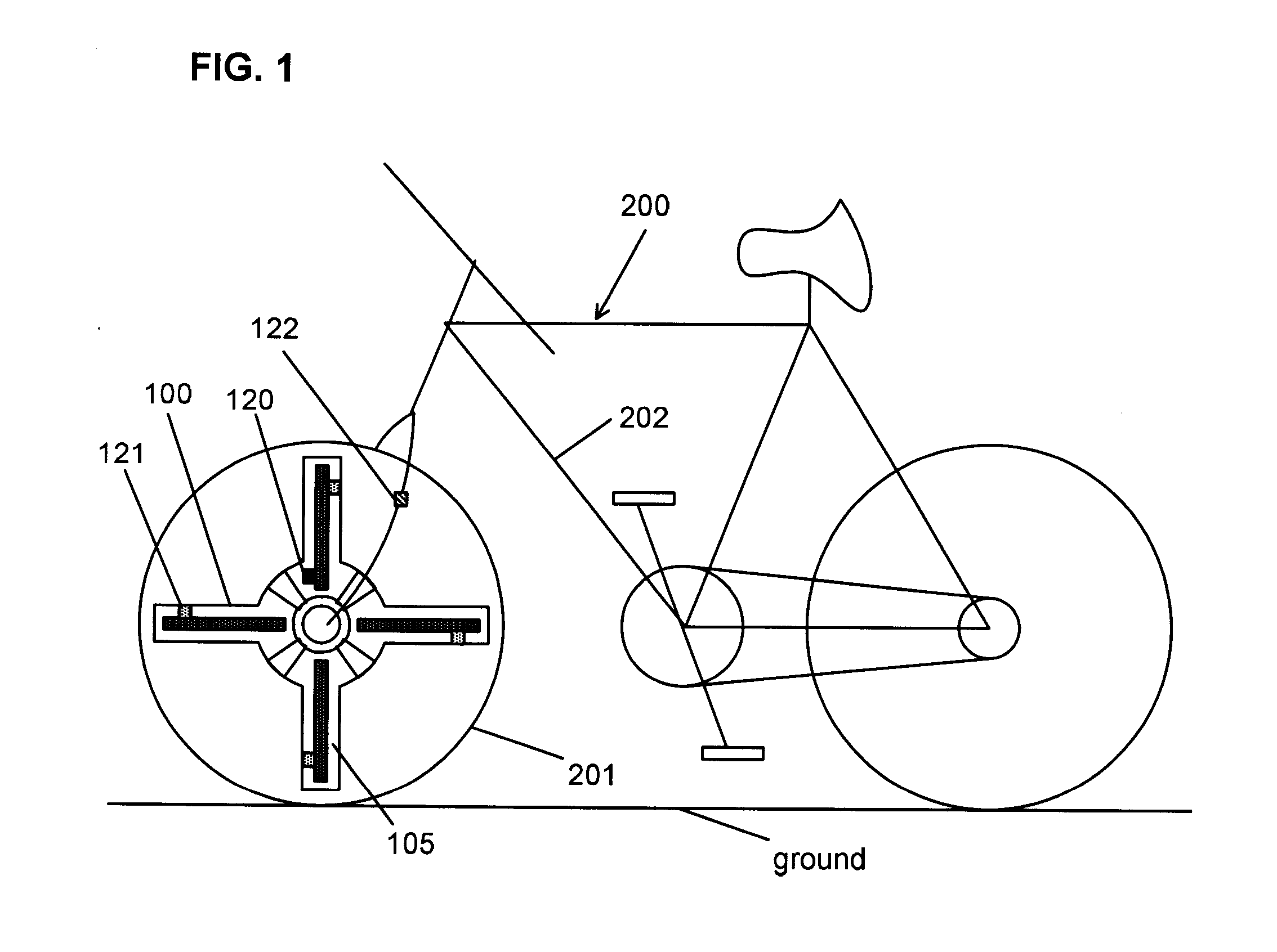
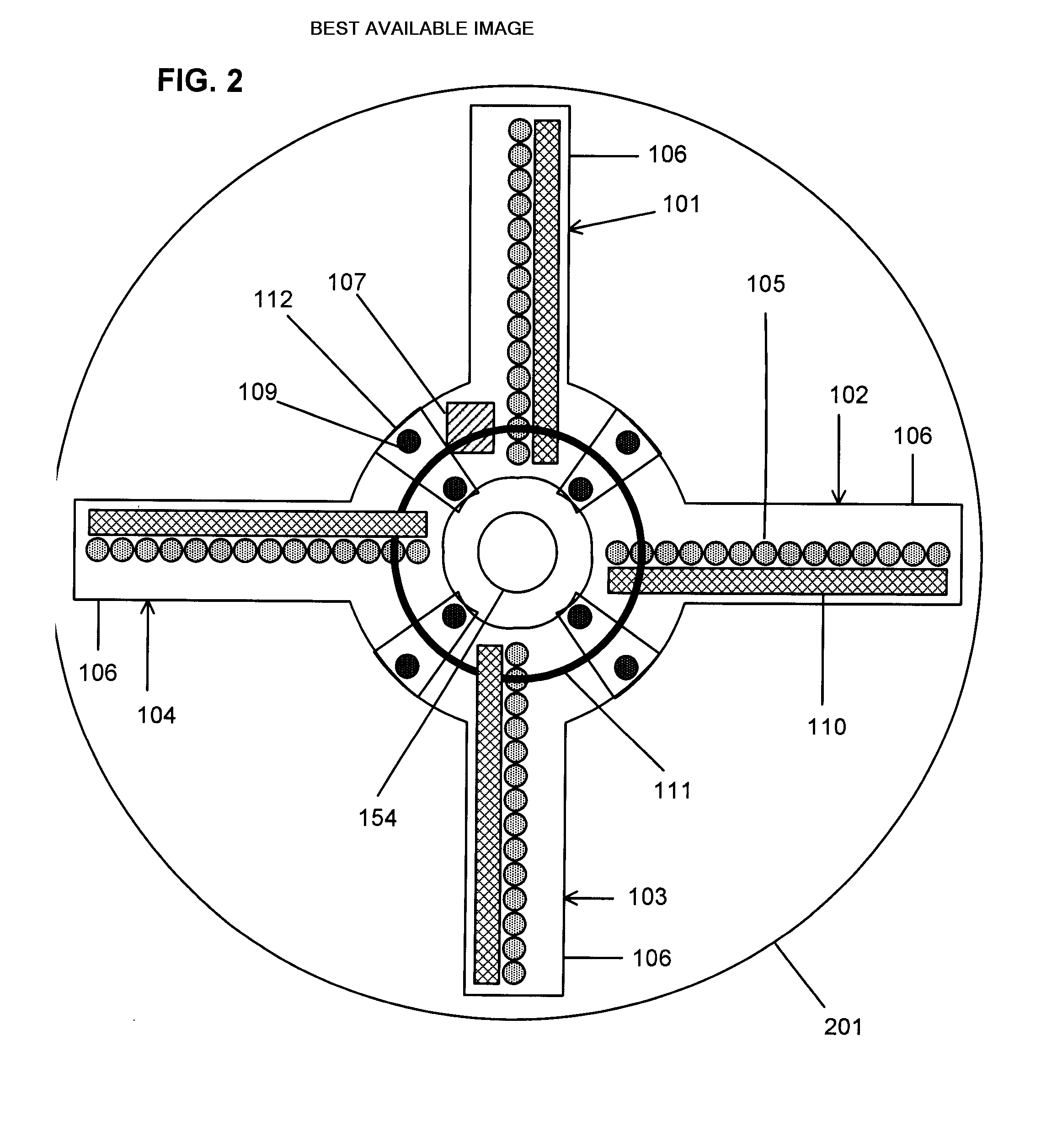
[0019]Also disclosed is a bicycle comprising a pair of rotating wheels each having spokes extending between a hub and a rim and a light display apparatus secured to one of the wheels. The light display apparatus comprises a set of at least two individual elongated light arrays, at least one of the elongated light arrays being a master light array. The elongated light arrays have two ends and at least one row of lights. The elongated light arrays have mechanical connections proximate one of the ends and mechanically connecting adjacent ones of the elongated light arrays and electrical connections proximate the mechanical connections and electrically connecting adjacent ones of the elongated light arrays. The set of individual elongated light arrays form a single rigid assembly. The single rigid assembly is attached to the spokes of the wheel as a unit. The set of elongated light arrays form an electrically conductive pathway traversing each of the elongated light arrays in the set. The electrically conductive pathway provides an electrical bus by which electrical power and electronic data can be shared between all of the elongated light arrays, and by which electronic data can be transmitted from the master array to each of the other elongated light arrays without an individual direct electrical connection. At least one sensor is mounted on the apparatus for determining angular velocity and position of the wheel. A microprocessor is mounted on the master light array and includes memory storing at least one of a display pattern and a display pattern generation computer code. The microprocessor modulates the rows of lights according to the display pattern or the display pattern generation computer code and sensed velocity and position of the wheel to form an image using persistence of vision of a viewer.
[0020]From the foregoing disclosure and the following more detailed description of various preferred embodiments it will be apparent to those skilled in the art that the present invention provides a significant advance in the technology and art of rotating wheel electronic displays. Particularly significant in this regard is the potential the invention affords for providing an easy to install, durable, reliable, and relatively inexpensive system. Additional features and advantages of various preferred embodiments will be better understood in view of the detailed description provided below.

Problems solved by technology

Its large single-piece circuit board is also comparatively very expensive to manufacture.
The device's small size simplifies its attachment to the wheel but limits the size and complexity of the display it is capable of producing.
Further, the device only emits light at one angular location on the wheel, which requires high rotation rates to produce a quality display.
The design of this device makes its use with bicycle wheels limited much like the Yu device.
The Hoch design has provided the highest displayed image quality of any bicycle wheel display available to date, however the Hoch has a number of problems that has limited its commercial success.
Specifically, when configured using only a single array of lights the Hoch design requires very high wheel rotation rates to form a solid display image.
Such rotation rates are inconvenient on a bicycle.
In the case where the arrays are electrically connected, the required cables are expensive and difficult to manufacture in a way which can survive the harsh environmental conditions experienced on a bicycle wheel.
In the case where the arrays are not electrically connected, each array requires its own microprocessor and batteries, significantly increasing cost and weight.
Whether electrically connected or not, the use of multiple physically separate arrays inherently causes difficult installation and configuration for the user, since each array must be individually attached to the wheel, aligned mechanically, and configured electronically.
Further, there is inherent excess weight due to the added hardware required for each array to be individually fully secured to the wheel, and inherently greater likelihood that an array will become loose.
When using multiple individual arrays of lights connected together, the Hoch design is further impractical for larger numbers of arrays as each slave array must be individually connected to the master array.
In order to allow the attachment of many slave arrays, many connectors are required on the master which adds to manufacturing cost and size, even though many users may never connect more than one or two slave arrays.

Method used


Image

  • Rotating wheel electronic display apparatus
  • Rotating wheel electronic display apparatus
  • Rotating wheel electronic display apparatus

Examples


Embodiment Construction

[0031]It will be apparent to those skilled in the art, that is, to those who have knowledge or experience in this area of technology, that many uses and design variations are possible for the rotating wheel electronic display apparatus disclosed herein. The following detailed discussion of various alternative and preferred embodiments will illustrate the general principles of the invention with reference to specific embodiments. Other embodiments suitable for other applications will be apparent to those skilled in the art given the benefit of this disclosure.

[0032]In this specification and claims, the term “POV” refers to the Persistence Of Vision effect of the human eye. In this specification and claims, the term “linear bus” refers to an electrically conductive pathway having the topology of a line. In this specification and claims, the term “loop bus” refers to an electrically conductive pathway having the topology of a loop. In this specification and claims, the terms “shared el...


PUM


Abstract

A light display is mounted on the spokes of a rotating bicycle wheel. The display includes a plurality of individual arrays of lights forming a set. The set of arrays are attached together into a single rigid light display apparatus attached to a spoke of the wheel at the tip of each array of lights. At least one sensors on the apparatus, senses the angular velocity and angular position of the rotating wheel. A microprocessor, is mounted on one of the arrays of lights and connected to the sensor, and is further connected to a shared electrical bus which traverses every array of lights. The shared electrical bus is formed by the electrical connection of all the arrays of lights in a line or loop topology. Each array of lights has at most two connection points to the shared electrical bus. The microprocessor modulates the plurality of arrays of lights via the shared electrical bus and without a direct connection to every array of lights. The arrays of lights are modulated according to a selected one of a plurality of display patterns and the sensed angular velocity and position of the rotating wheel, to form a stabilized, upright, forward-reading image on both sides of the wheel using persistence of vision of a viewer.

Description

CROSS-REFERENCE TO RELATED APPLICATIONS[0001]Not ApplicableSTATEMENT REGARDING FEDERALLY SPONSORED RESEARCH[0002]Not ApplicableREFERENCE TO MICROFICHE APPENDIX[0003]Not ApplicableFIELD OF THE INVENTION[0004]The field of the present invention relates to methods and display apparatus for producing displayed images within a rotating wheel using time / position multiplexing of lighting elements and persistence of vision of a viewer.BACKGROUND OF THE INVENTION[0005]The characteristic persistence of vision of human viewers has been used to advantage in previous display devices, including rotating wheel displays. U.S. Pat. No. 5,057,827 to Nobile et al., the disclosure of which is expressly incorporated herein in its entirety by reference, describes a motor actuated rotating member where an array of LEDs are turned on and off using time or position division multiplexing so that to an observer an image is generated over the path of the array.[0006]U.S. Pat. No. 5,302,965 to Belcher et al., th...

Claims


Application Information

Patent Timeline
Patent Type & Authority Applications(United States)
IPC IPC(8): B62J6/00G09G5/10
CPCB62J6/20G09G3/005G09F21/045
Inventor GOLDWATER, DAN
Owner PIKE BRANDS LLC
Learn More