Control device for controlling image display device, head-mounted display device, image display system, control method for the image display device, and control method for the head-mounted display device

a control device and display device technology, applied in image enhancement, instruments, computing, etc., can solve the problems of complicated configuration and control of control devices and image display devices, not easy to change the image display device connected to the control device, and the control device cannot normally control the image display device. achieve the effect of easy suppression

Active Publication Date: 2012-08-09
SEIKO EPSON CORP
View PDF10 Cites 39 Cited by
  • Summary
  • Abstract
  • Description
  • Claims
  • Application Information

AI Technical Summary

Benefits of technology

[0011]An advantage of some aspects of the invention is to realize the control of various image display devices with one control device. Another advantage of some aspects of the invention zs to easily suppress, in a head-mounted display device in which an image display device and a control device can be connected and disconnected, a deficiency of control of the image display device by the control device.

Problems solved by technology

Therefore, it is not easy to change the image display device connected to the control device.
However, for example, if image display control conditions (resolution and a frame rate, pixel arrangement, a scan direction, and a gamma value) are different because models of the plural image display devices are different from one another, it is likely that the control devices cannot normally control the image display devices.
However, the configurations and the control of the control devices and the image display devices are complicated.
The head-mounted display device can cause the user to recognize that the control of the image display unit actually connected to the control device cannot be normally performed.
Therefore, the control device can cause the user to recognize a problem of a connection correspondence relation between the control device and the image display device and a problem concerning display control and, according to necessity, urge the user to take measures.
If the image display device is the navigation display device, it is unnecessary to mount needless components on the navigation display device.
Therefore, in the image display system, even when the control device cannot control the image display device, the image display device causes the user to visually recognize the error image.
Therefore, it is easy to cause the user to recognize error notification.

Method used


Image

  • Control device for controlling image display device, head-mounted display device, image display system, control method for the image display device, and control method for the head-mounted display device
  • Control device for controlling image display device, head-mounted display device, image display system, control method for the image display device, and control method for the head-mounted display device
  • Control device for controlling image display device, head-mounted display device, image display system, control method for the image display device, and control method for the head-mounted display device

Examples


first embodiment

A. First Embodiment

[0059]A-1. Device Configuration

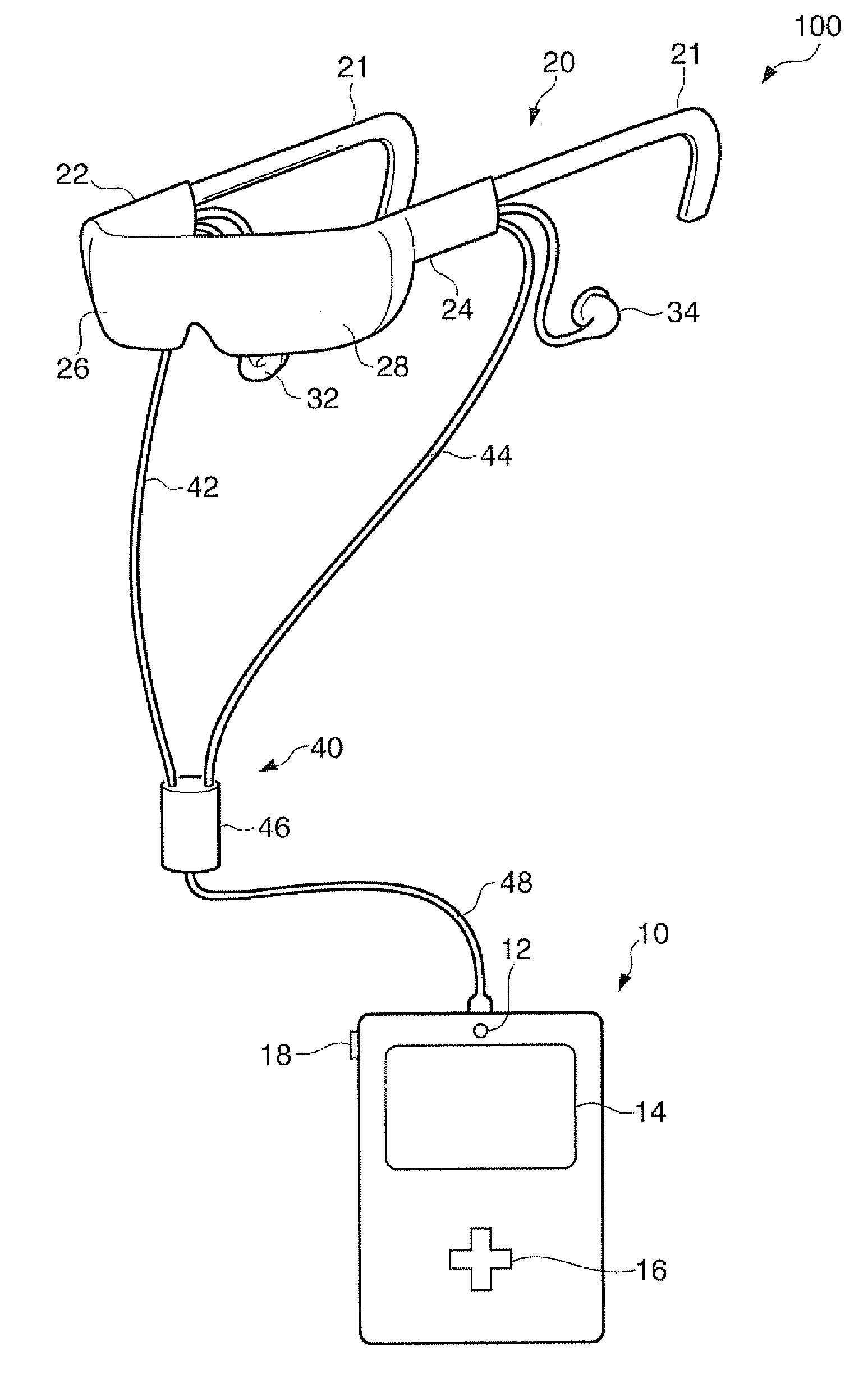
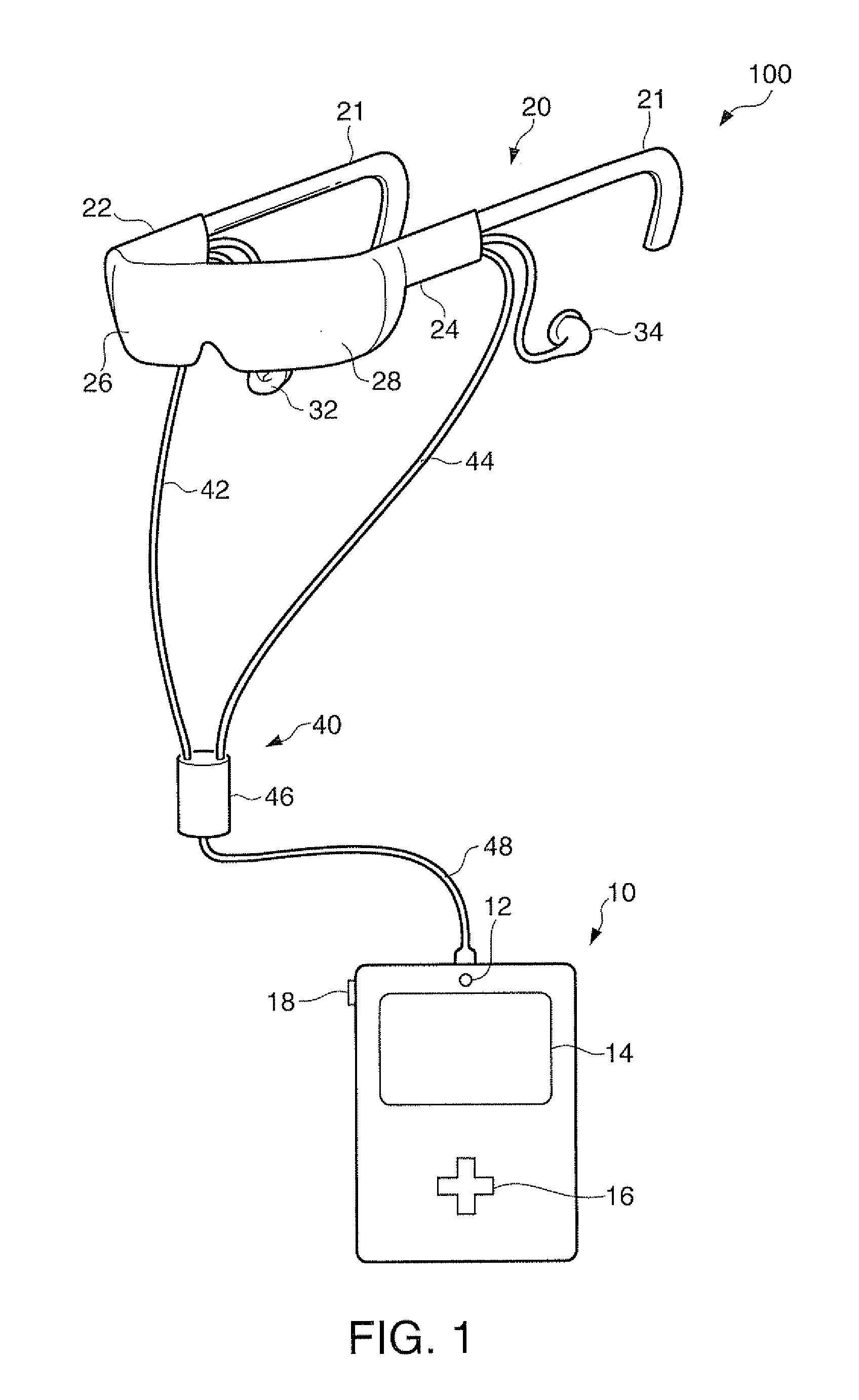
[0060]FIG. 1 is an explanatory diagram showing an external configuration of a head-mounted display device 100 in a first embodiment of the invention. The head-mounted display device 100 is a display device mounted on the head and is also called head-mounted display (HMD). The head-mounted display device 100 in this embodiment is an optical transmissive head-mounted display device with which a user can visually recognize a virtual image and, at the same time, directly visually recognize an external scene.

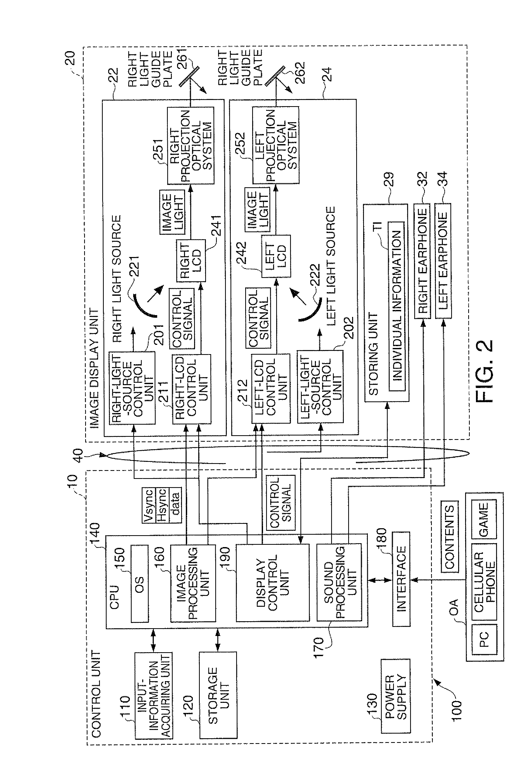
[0061]The head-mounted display device 100 includes an image display unit 20 that causes the user to visually recognize a virtual image on the basis of an image signal in a state in which the image display unit 20 is mounted on the head of the user and a control unit (a controller) 10 that controls the image display unit 20.

[0062]The image display unit 20 is a mounted member mounted on the head of the user. In this embodiment, the imag...

second embodiment

B. Second Embodiment

[0098]FIG. 6 is an explanatory diagram functionally showing the configuration of a head-mounted display device 100a in a second embodiment. The head-mounted display device 100a in the second embodiment is different from the head-mounted display device 100 in the first embodiment in content of individual information TIa of information stored in a storing unit 29a of an image display unit 20a. Otherwise, the head-mounted display device 100a is the same as the head-mounted display device 100. A control unit 10a in the second embodiment is equivalent to the control device and the control unit in the invention. The image display unit 20a is equivalent to the image display device in the invention.

[0099]FIG. 7 is an explanatory diagram illustratively showing the content of the individual information TIa in the second embodiment. As shown in FIG. 7, the individual information TIa in the second embodiment is different from the individual information TI in the first embodi...

third embodiment

C. Third Embodiment

[0114]FIG. 10 is an explanatory diagram showing an external configuration of a projector 50 functioning as a projection display device in a third embodiment. The projector 50 in the third embodiment is different from the head-mounted display device 100a in the second embodiment in that the image display device is the projector 50 and in content of individual information TIb. Otherwise, the projector 50 is the same as the head-mounted display device 100a.

[0115]The projector 50 includes a housing 800, a projection optical system 740 provided on the front surface of the housing 800, an operation unit 600 provided on an outer surface (e.g., the upper surface) of the housing 800, and a speaker 38 provided in the housing 800. The projector 50 is equivalent to the image display device in the invention that forms an image on the basis of an image signal. In the third embodiment, a control unit 10b is connected to the projector 50 by radio communication rather than by wir...


PUM


Abstract

A control device that controls an image display device that forms an image on the basis of an image signal includes: an acquiring unit that acquires, from the image display device, individual information for specifying a control form of the image display device connected to the control device; and a control unit that controls the image display device on the basis of the acquired individual information.

Description

BACKGROUND[0001]1. Technical Field[0002]The present invention relates to a control device that controls an image display device, a head-mounted display device, which is a display device mounted on the head, an image display system, a control method for the image display device, and a control method for the head-mounted display device.[0003]2. Related Art[0004]In the past, there is known a control device that connects the control device and an image display device in a one-to-one relation and controls image display on the image display device. A connection device that discriminates specifications of the image display device and generates an identification signal is provided between the control device and the image display device. This enables the control device to control various image display devices (see, for example, JP-A-06-274137).[0005]A head-mounted display device (a head mounted display), which is a display device mounted on the head, is known. For example, the head-mounted d...

Claims


Application Information

Patent Timeline
Patent Type & Authority Applications(United States)
IPC IPC(8): G06T5/00G09G5/00
CPCG09G3/001G09G3/006G02B2027/014G02B2027/0156G02B2027/0178G02B27/017
Inventor KIMURA, FUSASHI
Owner SEIKO EPSON CORP
Why Eureka
Try Eureka