Video signal processing method and device for processing luminance signal

Inactive Publication Date: 2007-12-11
JVC KENWOOD CORP A CORP OF JAPAN
View PDF13 Cites 9 Cited by
  • Summary
  • Abstract
  • Description
  • Claims
  • Application Information

AI Technical Summary

Benefits of technology

[0016]It is an object of the present invention to provide a video signal processing method and a video signal processing device each of which can easily suppress flickers based on the characteristic difference of a complimentary color filter by signal processing performed by a circuit arrangement.
[0017]It is another object of the present invention to provide a luminance signal processing circuit for a color video camera which can considerably suppress a false signal generated by luminance signal processing for a color video camera.
[0022]In the video signal processing method and the video signal processing device, the predetermined arithmetic operation is performed by using the output signal from the specific pixel of the solid state image pickup device and the output signals (or output signal from another specific pixel) of all the pixels, so that the control signal having a value corresponding to a characteristic difference of color filters is generated. Therefore, when a correction process is performed to a video signal by using the control signal, the characteristic difference of the color filters can be suppressed. As a result, flickers can be suppressed from being generated.

Problems solved by technology

Since the spectral difference as described above is caused by a characteristic difference between color filters of a complementary color filter arranged on a solid state image pickup device, it is very difficult (virtually, impossible) to correct the spectral difference by signal processing performed by a circuit arrangement.
Therefore, flickers cannot be suppressed.
Although a substantial resolution is determined by the number of pixels arranged on a CCD solid state image pickup device, after a sampling process and a restoring process, a false signal caused by an essentially high spatial frequency component is inevitably generated.

Method used


Image

  • Video signal processing method and device for processing luminance signal
  • Video signal processing method and device for processing luminance signal
  • Video signal processing method and device for processing luminance signal

Examples


first embodiment

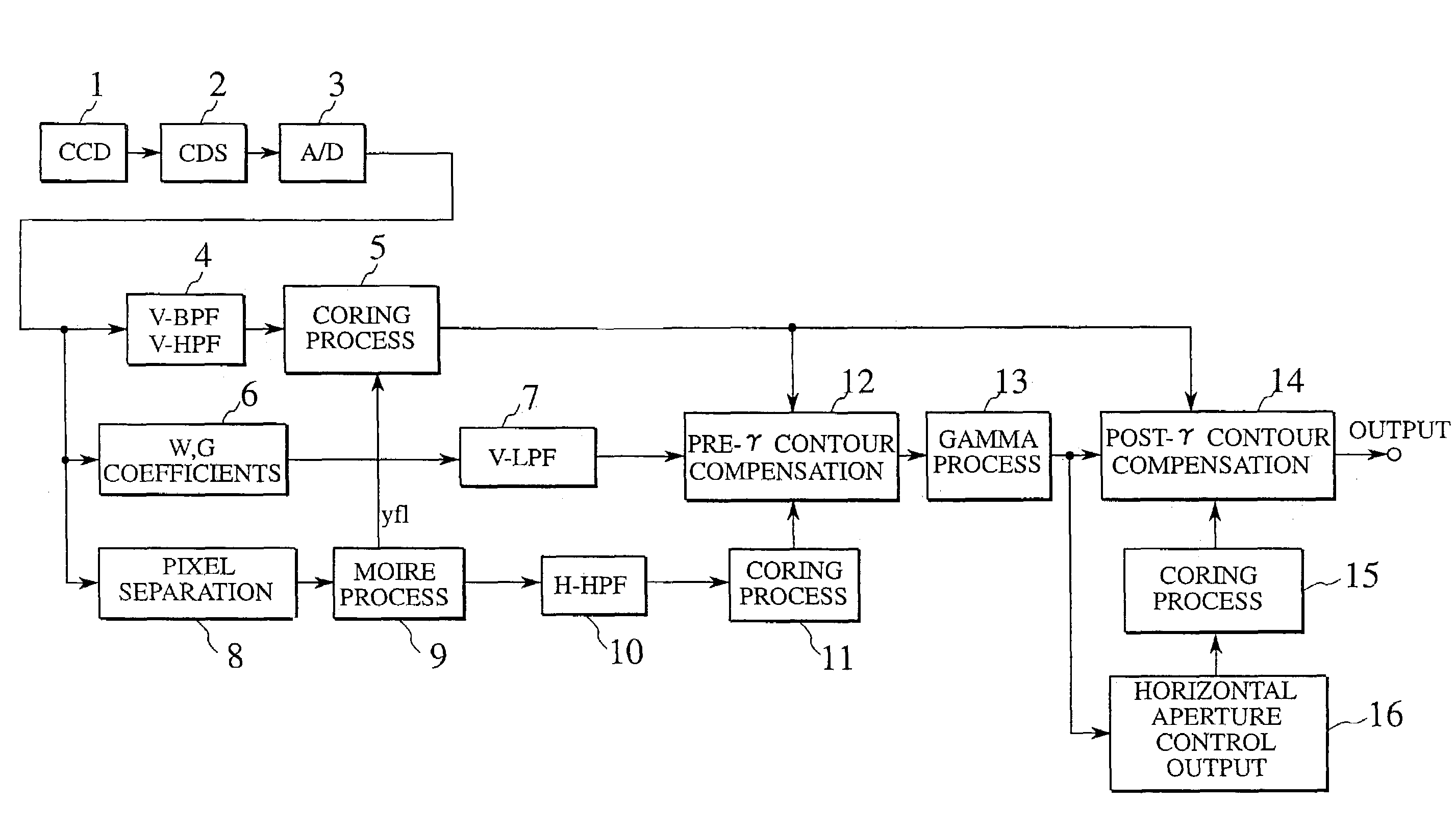
[0042]A video signal processing method and a video signal processing device according to the first embodiment of the present invention can be applied to a video camera in which a video signal picked up by, e.g., a solid state image pickup device (charge coupled device: CCD) is recorded on a tape-like recording medium such as a magnetic tape, a disk-like recording medium such as a magnetic disk or an optical disk, or a semiconductor memory or a removable semiconductor memory card arranged in the device.

[0043]A solid state image pickup device used in a video camera according to this embodiment employs a solid state image pickup device using a so-called all-pixel reading system which independently reads signal charges of all the pixels in a field period and outputs the signal charges without mixing them so that high horizontal and vertical resolutions of an object can be obtained, even if the object is quickly moving. In addition, in this embodiment, in order to reduce the size of the ...

second embodiment

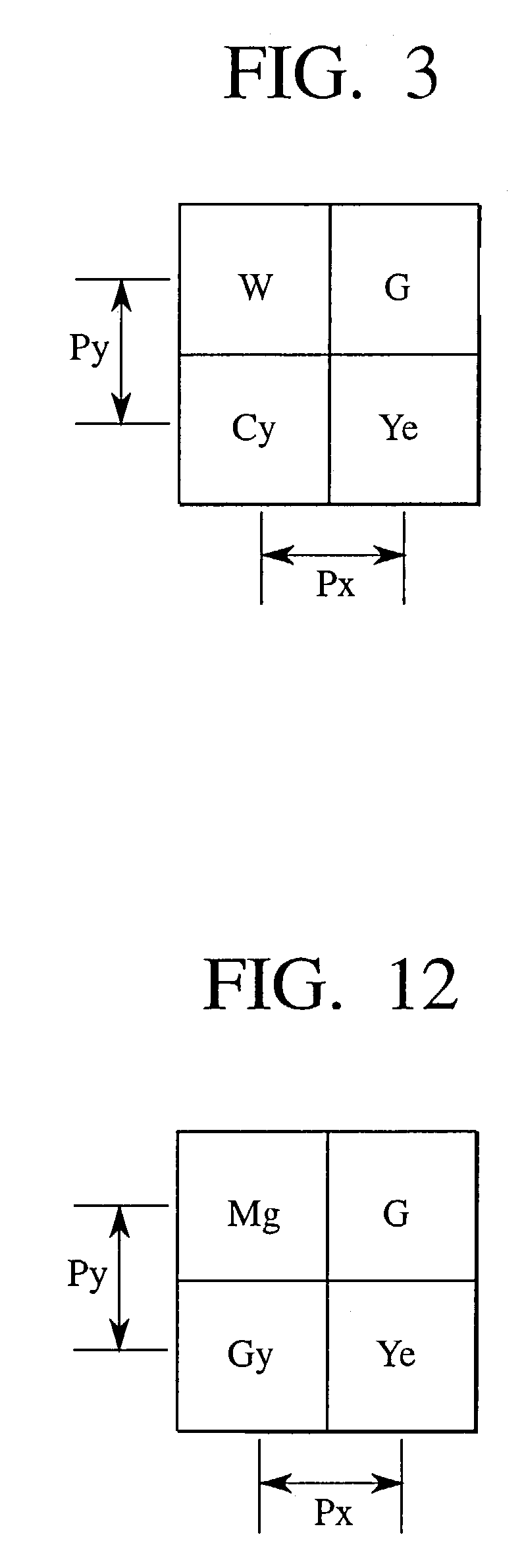
[0076]The second embodiment of the present invention will be described below with reference to FIGS. 10 to 12. FIG. 10 is a view showing the arrangement of the outline of the embodiment in which the present invention is applied to a color video camera. The same reference numerals as in FIG. 4 denote the same parts in FIG. 10, and an overlapping description will be omitted.

[0077]In this embodiment, as will be described later, a digital signal (to be referred to as a main signal hereinafter) from which a false signal is removed by a main signal processing circuit 6 is sequentially supplied to a vertical low-pass filter (V-LPF) 7a and a horizontal low-pass filter (H-LPF) 7b.

[0078]Since the vertical low-pass filter (V-LPF) 7a and the horizontal low-pass filter (H-LPF) 7b add a contour component, i.e., a high-frequency component to a main signal in a pre-γ contour compensation circuit 12 of the post stage, a high-frequency component is removed from the main signal as the previous proces...

third embodiment

[0096]The third embodiment of the present invention will be described below with reference to FIGS. 11 to 13. FIG. 13 is a view showing the arrangement of the outline of the third embodiment in which the present invention is applied to a color video camera. The same reference numerals as in FIGS. 4 and 10 denote the same parts in FIG. 13, and an overlapping description will be omitted.

[0097]In this embodiment, a signal output from a pixel separation circuit 8 and a signal from which a high-frequency component is removed through a horizontal low-pass filter (H-LPF) 8a is supplied to a moire process circuit 9.

[0098]A process for digital video signals sequentially supplied from the pixel separation circuit 8 will be described below in detail.

[0099]In Equation (1) described above, the first term is an original luminance signal, and the second term is a false signal generated by a folding component. Conversions given by the following equations are performed to respective pixels of input ...


PUM


Abstract

In a video signal processing method of processing a luminance signal of a video signal generated by causing a CCD to receive light transmitted through color filters, a control signal yf1 is generated by calculating Cy / Y using a complementary color signal Cy and a luminance signal Y, and coring correction is performed to the luminance signal by using the control signal yf1. The characteristic difference between the color filters is suppressed, and, as a result, flickers are suppressed from being generated.

Description

[0001]This application is a divisional application of U.S. patent application Ser. No. 09 / 203,718, filed Dec. 2, 1998, now U.S. Pat. No. 6,559,886, the contents of which are hereby incorporated by reference in its entirety.BACKGROUND OF THE INVENTION[0002]1. Field of the Invention[0003]The present invention relates to a video signal processing method and a video signal processing device each of which is applied to an image-pickup apparatus (e.g., video camera or the like) and performs a predetermined correction process to a luminance signal of a video signal generated by an image pickup operation performed by a solid state image pickup device.[0004]2. Description of Related Art[0005]Conventionally, in a so-called single-plate color video camera using only one sold state image pickup device (charge coupled device: CCD), color filters having different spectral characteristics are arranged on the solid state image pickup device in units of pixels, and signals depending on color compone...

Claims


Application Information

Patent Timeline
IPC IPC(8): H04N5/00H04N9/083H04N9/68H04N9/73H04N9/04
CPCH04N9/045H04N2209/046H04N23/843H04N25/136
Inventor MIYAHARA, HIROYUKI
Owner JVC KENWOOD CORP A CORP OF JAPAN
Why Eureka
Try Eureka