Temple of eyeglass frame

a technology of eyeglass frames and temples, applied in the field of temples of eyeglass frames, can solve the problems of high cost of eyeglass frames, difficulty in intelligent design of eyeglass frames, and difficulty in reducing production costs, etc., and achieves the effects of simple structure, easy suppression, and reduced production costs

Active Publication Date: 2011-10-25
FOUR NINES
View PDF18 Cites 9 Cited by
  • Summary
  • Abstract
  • Description
  • Claims
  • Application Information

AI Technical Summary

Benefits of technology

[0007]The present invention solves the problems mentioned above, and aims to provide a temple for an eyeglass frame which temple exerts an urging force onto a facial surface and has a simple structure to enable the manufacture and assembly thereof to be easy to suppress the production cost thereof to be inexpensive. Moreover, the present invention aims to provide a temple capable of maintaining the initial performance thereof for a long time without needing any maintenance. Furthermore, the present invention aims to provide a temple capable of being smartly designed.
[0012]By adopting the configurations mentioned above, the eyeglass frames of the present invention severally have a very simple structure to enable their manufacture and assembly to be easy, and consequently their costs can be suppressed to be inexpensive. Moreover, the eyeglass frames can maintain their initial performances for a long time without needing any periodical maintenance. Furthermore, the eyeglass frames can be smartly designed with high design properties owing to their unique shapes.

Problems solved by technology

However, because the structures of the spring hinges are complicated, the eyeglass frame mentioned above has the problem of taking a lot of trouble with the manufacture and assembly thereof to makes the cost thereof high.
Moreover, the eyeglass frame has the problem of needing periodical maintenance in order to maintain the initial performance thereof for a long time.
Furthermore, the spring hinge has the problem of enlarging the shapes of the temples to make it impossible to smartly design the eyeglass frame.

Method used


Image

  • Temple of eyeglass frame
  • Temple of eyeglass frame
  • Temple of eyeglass frame

Examples


first embodiment

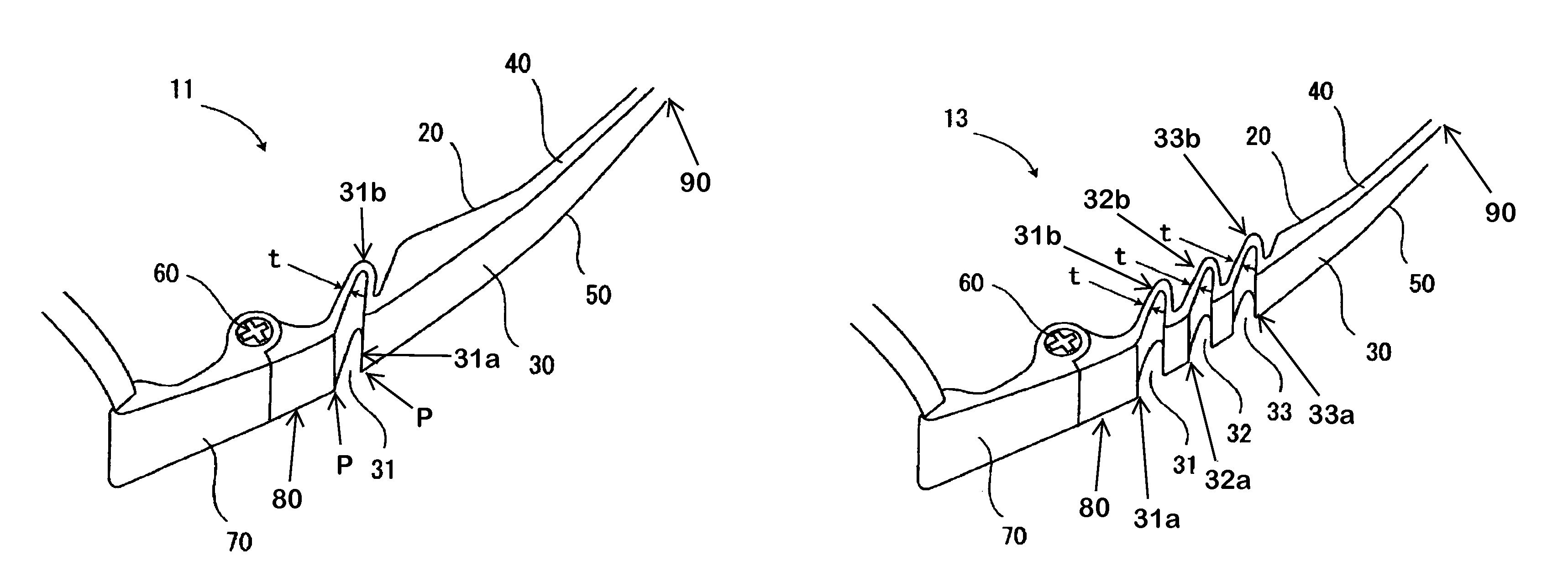
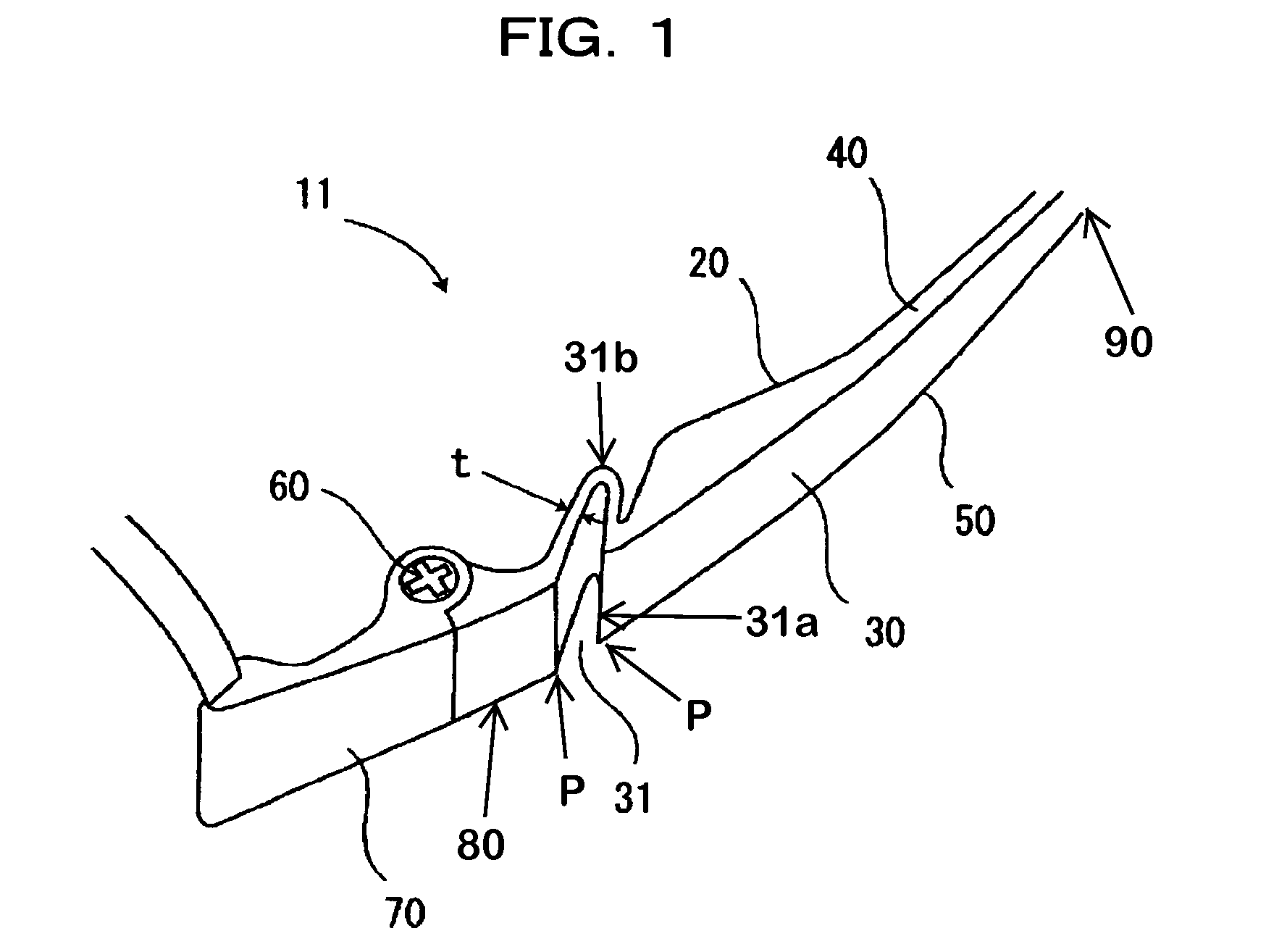
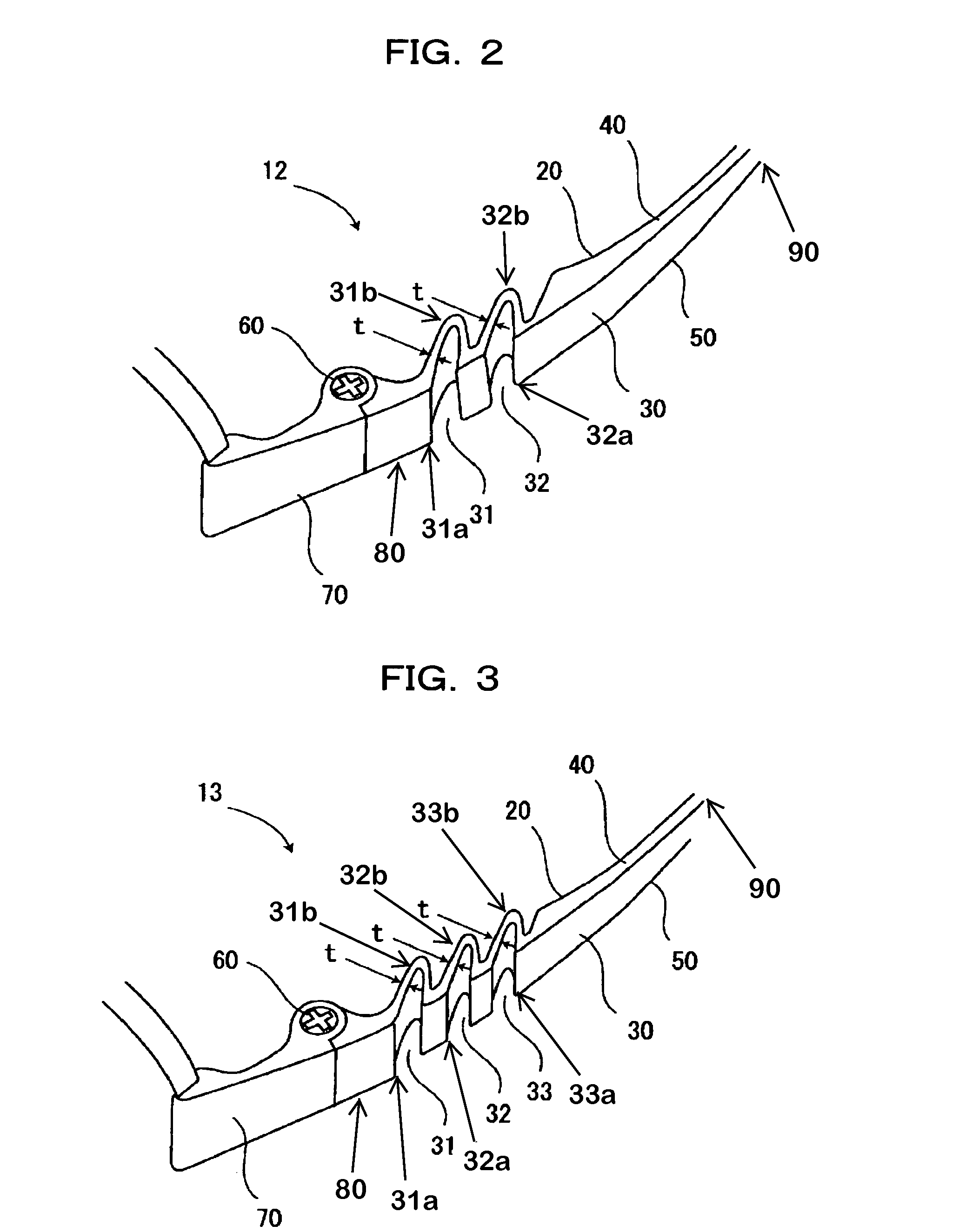
[0023]FIGS. 1-4C show temples according to the present invention. FIG. 1 shows a temple 11 for an eyeglass frame, where a first end 80 is linked to armor 70 with a hinge 60 put between them. The first end 80 and a second end 90 have four surfaces which are an inner surface 20, an outer surface 30, an upper surface 40, and a lower surface 50. The outer surface 30 has an outer surface concave portion 31 formed in a curved surface parallel to the rotation axis of the hinge 60 on a smooth flat surface or a curved surface. Outer surface concave portion 31 includes an opening 31a, which opens to the outer surface, and a bottom portion 31b, which is located in a position closer to the second end 90; whereas the opening 31a is positioned closer to the first end 80 as seen in FIG. 1. As further seen in FIG. 1, the corner that is formed by the outer surface 30 engaging the concave portion 31 at the curved surface of opening 31a is not a rounded edge. Instead, the corner forms a sharp point, P...

second embodiment

[0034]FIGS. 5-8C show temples according to the present invention. FIG. 5 shows a temple 15 for an eyeglass frame, one end of which is linked to the armor 70 with the hinge 60 put between them. The four surfaces of the inner surface 20, the outer surface 30, the upper surface 40, and the lower surface 50 are formed on the side of the end. The outer surface 30 has the outer surface concave portion 31 formed in a curved surface parallel to the rotation axis of the hinge 60 on a smooth flat surface or a curved surface. As seen in FIG. 5, the corner that is formed by the outer surface 30 engaging the concave portion 31 at the curved surface is not a rounded edge. Instead, the corner forms a sharp point, P. The inner surface 20 has an inner surface concave portion 21 formed in a curved surface parallel to the rotation axis of the hinge 60 on a smooth flat surface or a curved surface. Then, the boundary portion between the outer surface concave portion 31 and the inner surface concave port...


PUM


Abstract

A temple for an eyeglass frame exerts an urging force onto a facial surface, and has a simple structure to make the manufacture and assembly thereof easy. The temple can be provided at an inexpensive cost. The temple comprises four surfaces of an inner surface 20, an outer surface 30, an upper surface 40, and a lower surface 50 on one end side, which end is linked to armor 70 with a hinge 60 put between the end and the armor 70. The outer surface 30 has outer surface concave portions 31, 32, and 33, each formed in a curved surface parallel to the rotation axis of the hinge 60. The portions of the inner surface 20 corresponding to the outer surface concave portions 31, 32, and 33 are formed in curved surfaces parallel to the curved surfaces of the outer surface concave portions 31, 32, and 33 to form an almost uniform thickness between the portions.

Description

BACKGROUND OF THE INVENTION[0001]1. Field of the Invention[0002]The present invention relates to a temple for an eyeglass frame, and more particularly to a temple exerting an urging force onto a facial surface.[0003]2. Description of the Related Art[0004]There are various types of eyeglass frames. For example, an eyeglass frame equipped with a pair of ring-like rims, a bridge linking the inner edge portions of both of the rims together, and temples rotatably linked to the outer edge portions of both of the rims with spring hinges put between the temples and the outer edge portions has been known. The eyeglass frame disclosed in Japanese Patent Application Laid-Open Publication No. 2003-185981 is equipped with spring hinges each linking a temple and armor together, and is configured so that the tip of a blade spring provided on each of the temples abuts against the end of each piece of the armor at a predetermined position when the temple is opened.[0005]Then, if the temple is furthe...

Claims


Application Information

Patent Timeline
Patent Type & Authority Patents(United States)
IPC IPC(8): G02C5/16
CPCG02C5/16
Inventor IIMURA, YUICHI
Owner FOUR NINES
Why Eureka
Try Eureka