Starting device

a technology of starting device and starting shaft, which is applied in the direction of interengaging clutches, couplings, gearing, etc., can solve the problems of degrading the workability and assembly properties of parts, complicated clutch drum shape, etc., and achieves the effect of suppressing interference and facilitating interferen

Active Publication Date: 2014-09-11
AISIN AW CO LTD +2
View PDF4 Cites 8 Cited by
  • Summary
  • Abstract
  • Description
  • Claims
  • Application Information

AI Technical Summary

Benefits of technology

[0005]It is a primary object of the present invention to simplify the structure of a clutch drum of a multi-plate clutch and to allow main components of a damper device to which power from a motor is transmitted via the multi-plate clutch to be used also in a damper device to which the power from the motor is transmitted via a single-plate clutch.
[0009]The input element may have a contact portion extending toward the multi-plate clutch and contacting one end of the outer peripheral-side elastic body. This allows the input element to be placed without interfering with other members.
[0010]The intermediate element may be supported in axial and radial directions by the output element, and the clutch drum may be supported in the radial direction by the output element. Accordingly, since the intermediate member that is supported in the axial and radial directions by the output element is interposed between the clutch drum and the input element, the clutch drum and the input element can be supported in the axial direction by the intermediate member without performing special processing on the intermediate member. Moreover, since the clutch drum is supported in the radial direction by the output element, the input element that is coupled to the clutch drum can also be supported in the radial direction by the output element. This eliminates the need to perform special processing on the intermediate element and the output element in order to support the input element in the axial and radial directions, and the primary components such as the intermediate element, the output element, the outer peripheral-side elastic body, and the inner peripheral-side elastic body can be more easily used also in the damper device to which the power from the motor is transmitted via the single-plate clutch.
[0012]The first intermediate member may be supported in the radial direction by an axially extending portion formed in the clutch drum. This allows the first intermediate member to be easily supported in the radial direction by the clutch drum.
[0014]The multi-plate clutch may have a piston that moves toward a power input member connected to the motor and that presses a friction plate against the power input member. That is, such a multi-plate clutch is engaged by moving the piston toward the power input member. This can easily suppress interference between the multi-plate clutch and the damper device. Accordingly, combining the multi-plate clutch having such a configuration with the damper device according to the present invention eliminates the need to perform special processing on the intermediate element and the output element in order to suppress interference with the multi-plate clutch, and allows the primary components such as the intermediate element, the output element, the outer peripheral-side elastic body, and the inner peripheral-side elastic body to be easily used also in the damper device to which the power from the motor is transmitted via the single-plate clutch.

Problems solved by technology

However, the use of such a structure may complicate the shape of the clutch drum and may degrade workability and assembling properties of parts.

Method used


Image

  • Starting device
  • Starting device
  • Starting device

Examples


Embodiment Construction

[0020]A mode for carrying out the present invention will be described below by using an embodiment.

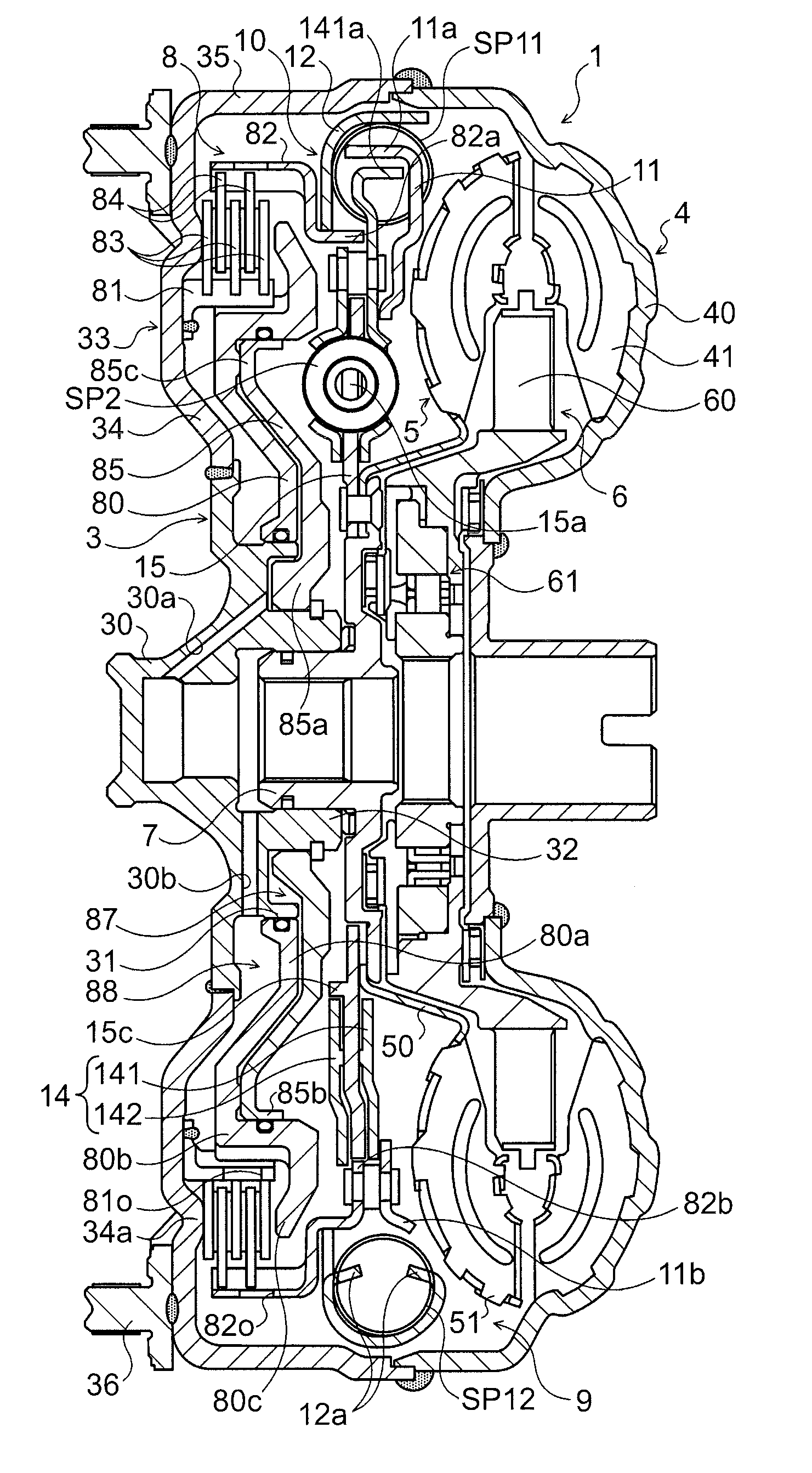
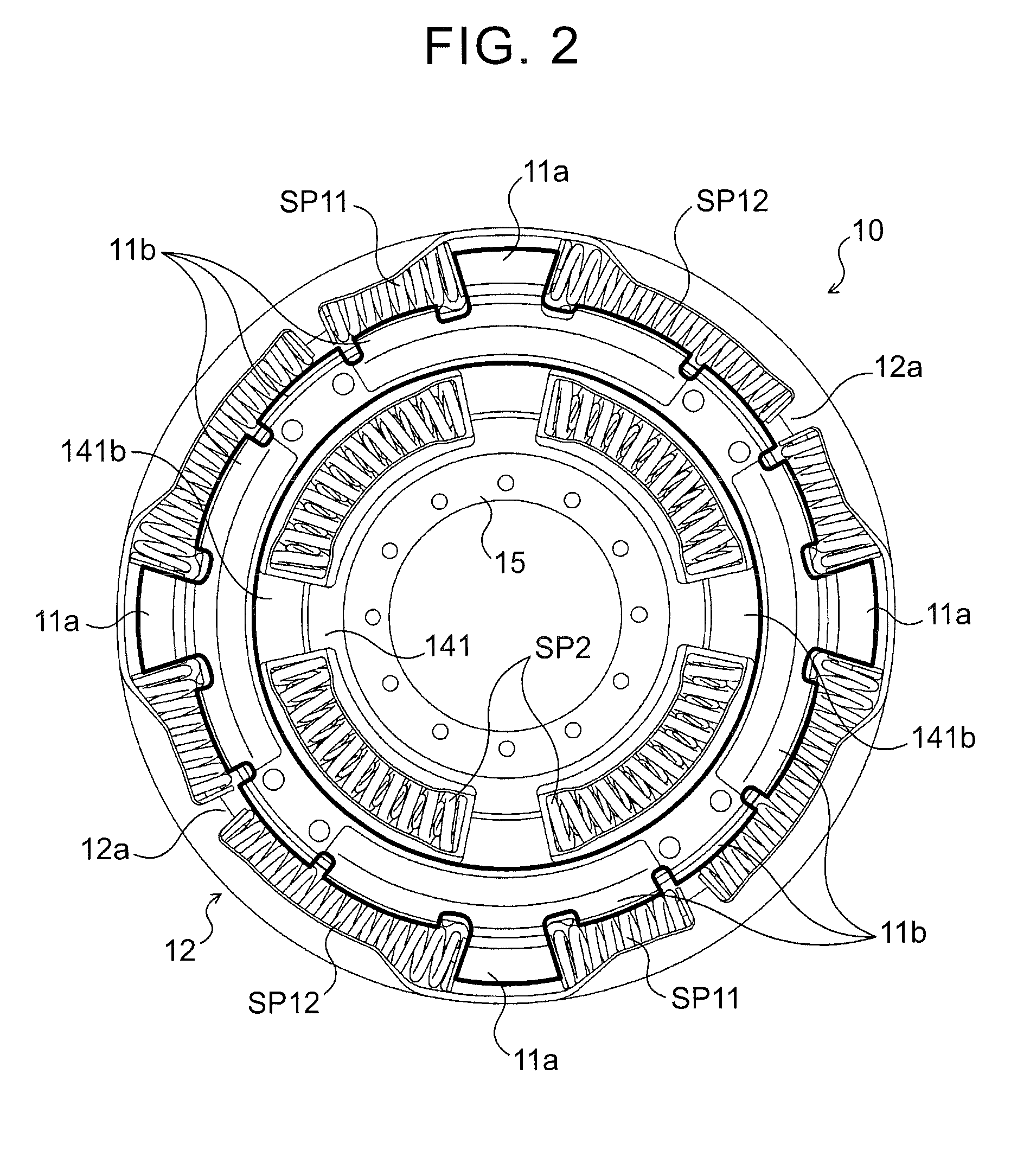
[0021]FIG. 1 is a configuration diagram showing a hydraulic transmission device 1 as a starting device according to an embodiment of the present invention. The hydraulic transmission device 1 shown in the figure is a torque converter that is mounted as a starting device on a vehicle including an engine (internal combustion engine) as a motor, and includes: a front cover (power input member) 3 that is connected to a crankshaft of the engine, not shown; a pump impeller (input-side hydraulic transmission element) 4 fixed to the front cover 3; a turbine runner (output-side hydraulic transmission element) 5 capable of rotating coaxially with the pump impeller 4; a stator 6 that regulates the flow of hydraulic oil (working fluid) from the turbine runner 5 to the pump impeller 4; a turbine hub (power output member) 7 that is fixed to an input shaft of a shift device as an automatic transmissi...


PUM


Abstract

A starting device configured with a multi-plate clutch and a damper device. The damper device may include an input element to which power from a motor is transmitted via the multi-plate clutch, an outer peripheral-side elastic body to which the power is transmitted from the input element, an inner peripheral-side elastic body that is placed on an inner peripheral side of the outer peripheral-side elastic body, an intermediate element that transmits the power from the outer peripheral-side elastic body to the inner peripheral-side elastic body, and an output element to which the power is transmitted from the inner peripheral-side elastic body. The input element may be coupled to a clutch drum of the multi-plate clutch so that the input element and the clutch drum interpose the intermediate element therebetween.

Description

TECHNICAL FIELD[0001]The present invention relates to starting devices that include a multi-plate clutch and a damper device.BACKGROUND ART[0002]Conventionally, devices including a multi-plate clutch that moves toward a front cover connected to a motor and presses a friction plate against the front cover and a damper device that is coupled to a clutch drum of the multi-plate clutch are known as this type of starting devices (see, e.g., Patent Document 1).RELATED ART DOCUMENTSPatent Documents[0003][Patent Document 1] German Patent Application Publication No. 102008060940SUMMARY OF THE INVENTION[0004]Although Patent Document 1 does not describe a specific configuration of the damper device, one way to transmit power from the multi-plate clutch to the damper device is to make the clutch drum directly contact an elastic body of the damper device. However, the use of such a structure may complicate the shape of the clutch drum and may degrade workability and assembling properties of part...

Claims


Application Information

Patent Timeline
Patent Type & Authority Applications(United States)
IPC IPC(8): F16D13/52F16D3/12
CPCF16D3/12F16D13/52F16H45/02F16F15/12313F16F15/12366F16F15/12373F16F15/134F16H41/28F16H2045/0231
Inventor ITO, KAZUYOSHIISHIKAWA, MASAHIROTANAKA, JUNJIKASASHIMA, FUMIMASAYAMASHITA, NAOHISAWATANABE, TAKESHI
Owner AISIN AW CO LTD
Why Eureka
Try Eureka