LC oscillator circuit with a compensation coil for parasitical collector capacitor

a technology of oscillator circuit and collector capacitor, which is applied in the direction of oscillator generator, pulse generator, pulse technique, etc., can solve problems such as temperature fluctuation, and achieve the effect of preventing temperature, frequency and amplitude fluctuations

a technology of oscillator circuit and collector capacitor, which is applied in the direction of oscillator generator, pulse generator, pulse technique, etc., can solve problems such as temperature fluctuation, and achieve the effect of preventing temperature, frequency and amplitude fluctuations

US7532080B2Inactive Publication Date: 2009-05-12SYNERGY MICROWAVE CORP

Image

  • LC oscillator circuit with a compensation coil for parasitical collector capacitor
  • LC oscillator circuit with a compensation coil for parasitical collector capacitor
  • LC oscillator circuit with a compensation coil for parasitical collector capacitor

Examples


Embodiment Construction

)

[0016]The invention is explained in more detail below by way of the embodiments shown in schematic drawings.

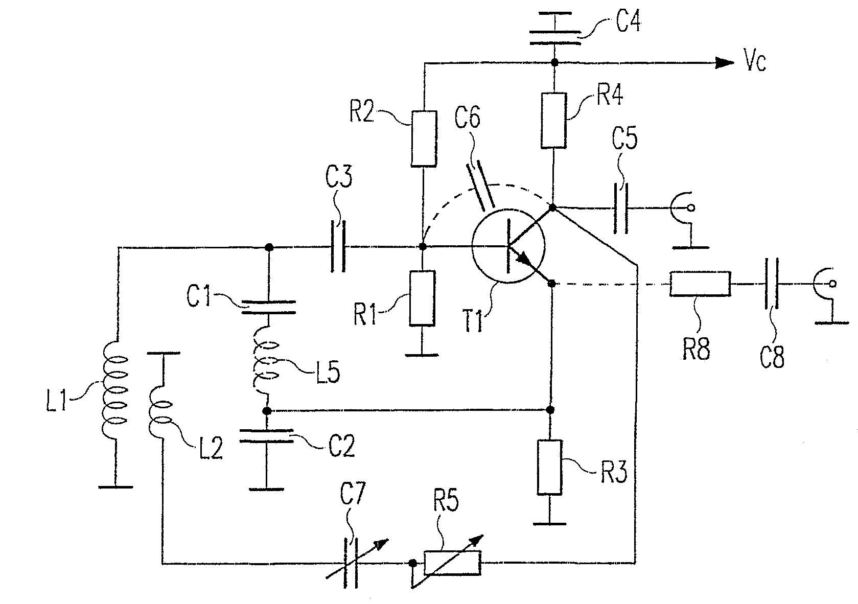
[0017]FIG. 1 shows the principle circuit diagram of a Colpitts oscillator with a parallel resonant circuit, consisting of an inductor L1 and the series circuit of two capacitors C1 and C2. A transistor T1 is used as an amplifier element, in the embodiment shown a bipolar npn-transistor. The resonant frequency of the oscillator is determined by L1 and C1 / C2. The operating point of the oscillator T1 is determined by the resistors R1, R2 and R3, through which also the supply voltage Vc is applied. If the output frequency is decoupled via the capacitor C5 on the collector of the transistor T1, a resistor R4 determining the output resistance is provided between collector and the capacitor C4. If decoupling occurs on the emitter of the transistor, as indicated by a dotted line in FIG. 1 through C8 and R8, this resistor R4 is superfluous and the collector of the transistor T1 is dir...


PUM


Abstract

An oscillator circuit configuration comprising in an LC-parallel oscillatory circuit and a transistor as an amplifying element. A compensating winding is associated with the parallel oscillatory circuit whereby the collector voltage of the transistor is fed to said winding in order to compensate the effect of the parasitic collector capacity. Preferably, the collector current from the transistor is maintained constant be an amplifier.

Description

CROSS REFERENCE TO RELATED APPLICATION(S)[0001]This application is a Divisional of and claims priority to U.S. Utility patent application Ser. No. 10 / 332,656, filed Apr. 1, 2003, now U.S. Pat. No. 7,102,453 which is a §371 National Phase Application of PCT Application Ser. No.: PCT / EP00 / 07578 filed Aug. 4, 2000 which is turn claims priority to German Patent Application Ser. No,: 100 33 741.4 filed Jul. 12, 2000. The entire disclosure of all these documents is herein incorporated by reference.BACKGROUND OF THE INVENTION[0002]1. Field of the Invention[0003]The invention relates to an oscillator circuit with an LC-parallel resonant circuit and a transistor (T1) as amplifier element.[0004]2. Description of the Prior Art[0005]Oscillator circuits with LC-parallel resonant circuits with different types of feedback circuits are known. An example of these is the so-called Colpitts oscillator, in which the feedback circuit between the amplifier element consisting of one or several bipolar or ...

Claims


Application Information

Patent Timeline
12 May 2009
Publication
US7532080B2
IPC
H03B5/04; H03B5/12
CPC
H03B5/04; H03B5/1231; H03B5/1203; H03B5/124
Inventors
RHODE, ULRICH L.; DANZEISEN, KLAUS