Vibration structure of electrical toothbrush

Pending Publication Date: 2021-08-05
JIASHAN WANSHUNDA ELECTRONICS CO LTD
View PDF2 Cites 0 Cited by
  • Summary
  • Abstract
  • Description
  • Claims
  • Application Information

AI Technical Summary

Benefits of technology

[0007]It is therefore a primary object of the present invention to provide a vibration structure of electrical toothbrush, which can greatly prolong the lifetime of the electrical toothbrush.
[0008]It is a further object of the present invention to provide the above vibration structure of electrical toothbrush, which can greatly lower noise. To achieve the above and other objects, the vibration structure of electrical toothbrush of the present invention includes a shaft rod, a rocking rod, a fixing member and a vibration stem. The shaft rod has a first end and a second end. A driving power is applied to the first end to drive and vibrate the shaft rod. One end of the rocking rod is correspondingly inserted in the second end of the shaft rod. A weight block is disposed at the other end of the rocking rod. The weight block is eccentrically arranged to cause unbalance of the rocking rod to deflect from a central axis of the shaft rod. The fixing member is fitted on the rocking rod between the shaft rod and the weight block. The vibratio

Problems solved by technology

The weight block is eccentrically arranged to cause unbalance of

Method used


Image

  • Vibration structure of electrical toothbrush
  • Vibration structure of electrical toothbrush
  • Vibration structure of electrical toothbrush

Examples


Example

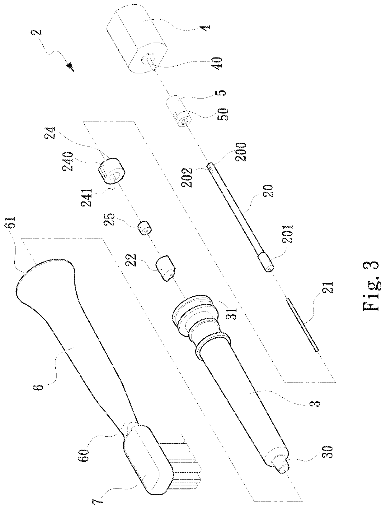
[0022]Please refer to FIGS. 3 to 6. FIG. 3 is a perspective exploded view of a first embodiment of the vibration structure of electrical toothbrush of the present invention. FIG. 4 is a perspective assembled view of the first embodiment of the vibration structure of electrical toothbrush of the present invention. FIG. 5 is a sectional view of the first embodiment of the vibration structure of electrical toothbrush of the present invention. FIG. 6 is an enlarged view of circled area of FIG. 5. According to the first embodiment, the vibration structure 2 of electrical toothbrush of the present invention includes a shaft rod 20, a rocking rod 21, a fixing member 24 and a vibration stem 3. The shaft rod 20 has a first end 200 and a second end 201. A drive unit 4 is disposed at the first end 200. The drive unit 4 serves to generate and output a drive power to drive the shaft rod 20 to rotate.

[0023]One end of the rocking rod 21 is correspondingly disposed at the second end 201 of the shaf...


PUM


Abstract

A vibration structure of electrical toothbrush includes a shaft rod, a rocking rod, a fixing member and a vibration stem. The shaft rod has a first end and a second end. A driving power is applied to the first end to drive and vibrate the shaft rod. One end of the rocking rod is correspondingly inserted in the second end of the shaft rod. A weight block is disposed at the other end of the rocking rod. The weight block is eccentrically arranged to cause unbalance of the rocking rod to deflect from a central axis of the shaft rod. The fixing member is fitted on the rocking rod between the shaft rod and the weight block. The vibration stem is formed with an internal first space. The shaft rod is correspondingly disposed in the first space with the fixing member in contact with inner side of the vibration stem.

Description

[0001]This application claims the priority benefit of Taiwan patent application number 109103570 filed on Feb. 5, 2020.BACKGROUND OF THE INVENTION1. Field of the Invention[0002]The present invention relates generally to a vibration structure, and more particularly to a vibration structure of electrical toothbrush, which can greatly prolong the lifetime of the electrical toothbrush.2. Description of the Related Art[0003]The electrical toothbrush has the advantage that the electrical toothbrush is non-manually operable to mechanically vibrate and produce bubbles from the toothpaste so as to clean up a user's oral cavity. Please refer to FIGS. 1 and 2, which show the vibration structure 1 of a conventional electrical toothbrush. The conventional electrical toothbrush has a vibration stem 10. A shaft rod 11 is disposed in the internal space of the vibration stem 10. A rocking rod 12 is disposed at one end of the shaft rod 11. A weight block 13 is disposed at the front end of the rocking...

Claims


Application Information

Patent Timeline
IPC IPC(8): A46B13/02A46B9/04A61C17/16
CPCA46B13/023A61C17/16A46B9/04A61C17/3481A61C17/222
Inventor WANG, WEI-CHUANWEI, QIANG
Owner JIASHAN WANSHUNDA ELECTRONICS CO LTD
Why Eureka
Try Eureka