Bearing roller ball base surface superfinishing mechanism

A technology of bearing rollers and ball bases, which is applied in the field of superfinishing of bearing rollers and ball bases, can solve problems such as limiting the machining accuracy of superfinishing machines, mutual interference, and reduced machining accuracy of roller ball bases, and achieves improved The effect of improving the processing quality of rollers, improving the processing accuracy, and improving the super precision

Inactive Publication Date: 2019-12-24
ZHEJIANG 81 PRECISION MACHINERY CO LTD
View PDF2 Cites 0 Cited by
  • Summary
  • Abstract
  • Description
  • Claims
  • Application Information

AI Technical Summary

Problems solved by technology

[0008] 1. A single oscillating mechanism drives a single oil stone to oscillate, which will cause the amplitude and frequency of the oil stones to be inconsistent, and affect the consistency of the machining accuracy of the roller ball base surface;
[0009] 2. During the oscillation process, only one oil stone is driven to oscillate, while there are multiple oil stones installed on the superfinishing machine, the oscillation frequency between the oil stones is inconsistent, and they will interfere with each other, resulting in a reduction in the machining accuracy of the roller ball base surface;
[0010] 3. When the drive wheel and the groove on the sheave are installed together, it is necessary to ensure that the drive wheel rotates freely in the groove. Therefore, there must be a fit gap, and the super-finishing machine itself is a super-finishing device, and the existing fit gap will limit the super-finishing machine processing accuracy;
[0011] 4. The driving wheel cooperates with the groove on the sheave, and can only drive the whetstone clip to vibrate along the guide of the groove, and cannot realize the adjustable amplitude of the whetstone clip vibration

Method used


Image

  • Bearing roller ball base surface superfinishing mechanism
  • Bearing roller ball base surface superfinishing mechanism
  • Bearing roller ball base surface superfinishing mechanism

Examples


Embodiment 1

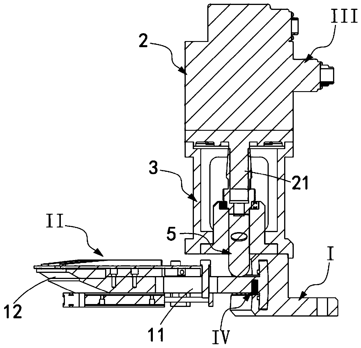
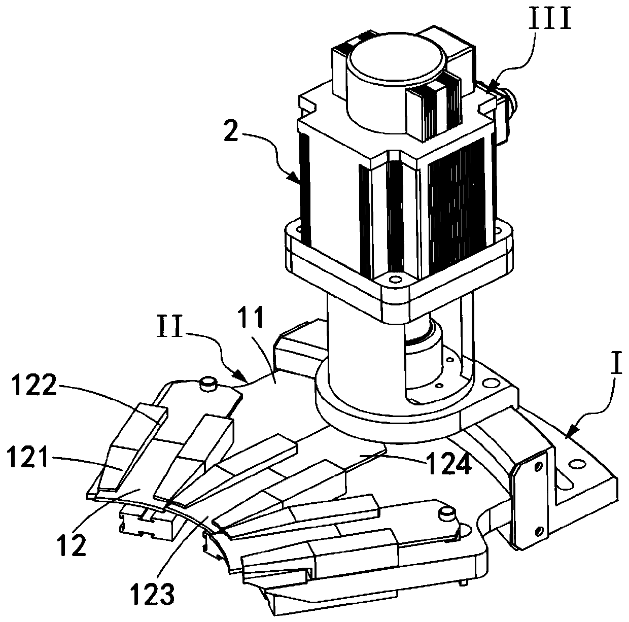
[0057] Such as Figure 1 to Figure 8 As shown, a bearing roller ball base surface super-precision mechanism includes a mounting base I and a super-precision component II installed on the mounting base I, and also includes an oscillating component III and a reset component IV;

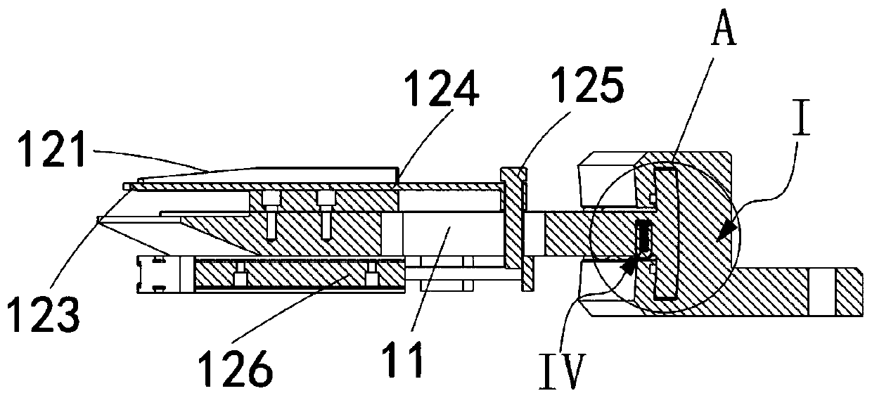
[0058] The ultra-precision component II includes a shroud 11 installed on the installation base I and at least one set of ultra-precision units 12, the shroud 11 is vertically movable relative to the installation base I, and the The ultra-precision unit 12 is arranged along the side of the surrounding plate 11 close to the base surface of the roller ball to be super-precision, and the other side edge of the surrounding plate 11 relative to the ultra-precision unit 12 is installed to always conflict with the mounting seat I. The coordinated reset component IV;

[0059] The oscillating assembly III is installed on the mounting base I, which includes a vertically arranged rotary drive device 2, an amplitu...

Embodiment 2

[0080] Figure 9 It is a structural schematic diagram of Embodiment 2 of a bearing roller ball base surface super-precision mechanism of the present invention; as Figure 9 As shown, the parts that are the same as or corresponding to those in Embodiment 1 use the reference numerals corresponding to Embodiment 1. For the sake of simplicity, only the differences from Embodiment 1 will be described below. This embodiment two and figure 1 The difference of the shown embodiment one is:

[0081] Such as Figure 9 As shown, a bearing roller ball base superfine mechanism, the control part 41 is a ball installed on the lower end of the rotating shaft 21 .

[0082] It should be noted that, different from the first embodiment, the control part 41 in this embodiment is a ball structure, which is directly rolled and placed in the groove at the lower end of the rotating shaft 21 .

[0083] It should be noted that, compared with the control part 41 provided with bumps, the control part 41 ...

Embodiment 3

[0085] Figure 10 It is a structural schematic diagram of Embodiment 3 of a bearing roller ball base surface super-precision mechanism of the present invention; as Figure 10 As shown, the parts that are the same as or corresponding to those in the second embodiment are marked with the corresponding reference numerals in the second embodiment. For the sake of simplicity, only the differences from the second embodiment will be described below.

[0086] Such as Figure 10 and Figure 11 As shown, a bearing roller base surface super-precision mechanism further includes an elastic connection assembly 6 coaxially sleeved on the outside of the rotating shaft 21 through a tapered structure.

[0087] Further, the control part 41 is a protrusion extending outward from the lower end of the elastic connection component 6 or a ball rotatably mounted on the lower end of the elastic connection component 6 .

[0088] It should be noted that, in this embodiment, the control unit 41 can als...


PUM


Abstract

The invention provides a bearing roller ball base surface superfinishing mechanism. The bearing roller ball base surface superfinishing mechanism comprises a mounting base and a superfinishing assembly mounted on the mounting base. The bearing roller ball base surface superfinishing mechanism further comprises an oscillation assembly and a reset assembly. The superfinishing assembly comprises a coaming mounted on the mounting base and at least one set of superfinishing unit. The oscillation assembly is mounted on the mounting base. A plurality of sets of superfinishing units are arranged, andoilstones of the multiple sets of the superfinishing units are arranged on the coaming according to roller motion path trajectories so that the roller ball base surface can be ground along a curvilinear path. Meanwhile, the oscillation assembly is matched to drive all the superfinishing units to conduct fixed-amplitude oscillation grinding synchronously in the vertical direction. The effect that the amplitude of the oilstones is consistent to the frequency of vibrations is guaranteed, superfinishing precision of the roller ball base surface is improved and roller machining quality is also improved.

Description

technical field [0001] The invention relates to the technical field of superfinishing the base surface of bearing rollers, in particular to a superfinishing mechanism for the base surface of bearing rollers. Background technique [0002] Since the speed of the high-speed rail is as high as 200km / h, when selecting the bearing used for the wheel of the high-speed rail, the machining accuracy of the ball base surface of the bearing will be higher than that of the ordinary bearing, so as to meet the high-speed rail when turning and meeting cars. load carrying requirements. [0003] The processing method commonly used in the superfinishing of the bearing roller ball base surface is to complete the rough grinding, finishing and superfinishing processes on a superfinishing machine, and during the rough grinding, finishing and superfinishing process, Grinding process is carried out with rough oil stone grinding wheel, essential oil stone and ultra-fine oil stone. [0004] In the p...

Claims


Application Information

Patent Timeline
Patent Type & Authority Applications(China)
IPC IPC(8): B24B35/00B24B41/00
CPCB24B35/00B24B41/00
Inventor 陈仁波邓德祥闵鹏飞刘绿林王兵宗煜景王德东
Owner ZHEJIANG 81 PRECISION MACHINERY CO LTD
Why Eureka
Try Eureka